
A second combustion chamber structure device for hazardous waste incineration

A technology of a secondary combustion chamber and a drying device, applied in the field of combustion furnaces, can solve the problems of reducing the cross-sectional area of ​​the flue, increasing the cost, and serious flue gas disturbance, so as to reduce the cost of landfill disposal, reduce the cost of enterprise management, and avoid accumulation. The effect of ash and coking

Active Publication Date: 2021-09-21
上海域德环保股份有限公司
View PDF0 Cites 0 Cited by
  • Summary
  • Abstract
  • Description
  • Claims
  • Application Information

AI Technical Summary

Problems solved by technology

In addition, the upper cylinder of the second combustion chamber will also have molten material flowing from top to bottom, falling under the action of gravity, and also falling on the slope at the same time. The molten material adheres and accumulates layer by layer on the slope until it reaches a certain level. Thick coking material, the hardness of the coking material is very high, it is difficult to clean it online. With the gradual increase of the coking material, the circulation area of ​​the flue gas is reduced, and it even overlaps with the outlet of the rotary kiln. In severe cases, the rotary kiln will be shut down directly. turn, resulting in serious operational failures, damage to the incineration working conditions of the system, and safety accidents
[0003] From the main body of the secondary combustion chamber to the exit flue of the secondary combustion chamber, the flue gas flow section will decrease rapidly, and the flue gas flow rate will increase, resulting in serious disturbance of the flue gas inside the exit flue of the secondary combustion chamber, and the high-temperature flue gas incinerated by the secondary combustion chamber The gas is highly viscous, and the fly ash in the flue gas will adhere to the surface of the flue, resulting in serious ash accumulation and blockage. The temperature of the flue is above 1100°C. If the deposited fly ash cannot be removed in time, the The ash continues to burn under the high-temperature flue gas. When the melting point of the fly ash is low, it will form a melt, which will cause serious coking and reduce the cross-sectional area of ​​the flue. In severe cases, the flue may be blocked. It directly leads to the unstable negative pressure of the incinerator system, the reduction of incineration capacity, and the reduction of corporate profits. At the same time, there are potential safety hazards caused by unstable negative pressure.
The slag produced by hazardous waste incineration is still hazardous waste and needs to be sent to the hazardous waste landfill for landfill disposal. The disposal fee is charged according to the weight. The disposal fee is usually 3000-4000 yuan / ton, and the moisture absorbed by the slag is also charged according to the disposal fee. Calculate the weight charge, which greatly increases the cost of business operations

Method used


Image

  • A second combustion chamber structure device for hazardous waste incineration
  • A second combustion chamber structure device for hazardous waste incineration
  • A second combustion chamber structure device for hazardous waste incineration

Examples


Embodiment Construction

[0026] The following will clearly and completely describe the technical solutions in the embodiments of the present invention with reference to the accompanying drawings in the embodiments of the present invention. Obviously, the described embodiments are only some, not all, embodiments of the present invention. Based on the embodiments of the present invention, all other embodiments obtained by persons of ordinary skill in the art without making creative efforts belong to the protection scope of the present invention.

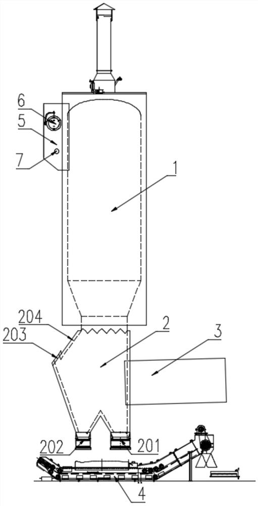
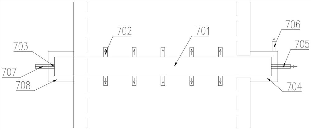
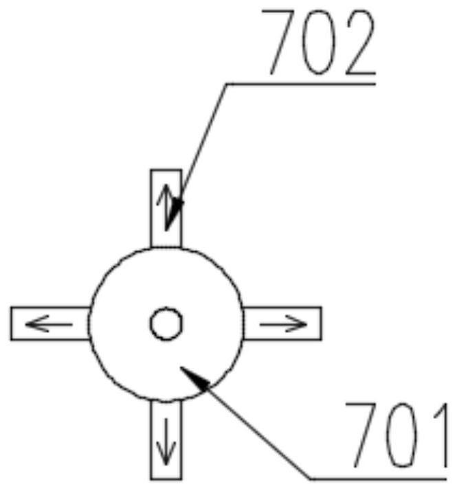
[0027] see figure 1 , a hazardous waste incineration secondary combustion chamber structure device, comprising a secondary combustion chamber upper cylinder 1, a secondary combustion chamber lower box 2, a secondary combustion chamber inlet 3, a secondary combustion chamber outlet 5, a first slag extractor 201 and a second combustion chamber Slagging machine 202, the second combustion chamber lower box 2 is arranged under the second combustion chamber upper cy...


PUM


Abstract

The invention discloses a hazardous waste incineration secondary combustion chamber structure device, which belongs to the technical field of combustion furnaces. The present invention comprises the upper cylinder body of the second combustion chamber, the lower box body of the second combustion chamber, the inlet of the second combustion chamber, the outlet of the second combustion chamber, the first slag discharger and the second slag discharger, and the upper cylinder of the second combustion chamber is provided with a The lower box of the second combustion chamber, one side of the lower box of the second combustion chamber is provided with the inlet of the second combustion chamber, the upper part of the upper cylinder of the second combustion chamber is provided with the outlet of the second combustion chamber, and the lower box of the second combustion chamber is provided with an outlet of the second combustion chamber. The bottom end is provided with a first slag extractor and a second slag extractor, the first slag extractor is close to the entrance of the second combustion chamber, and the second slag extractor is away from the entrance of the second combustion chamber. The invention has a simple and reasonable structure, increases the distance from the entrance of the second combustion chamber to its relative slope, reduces the coking of the second combustion chamber, and installs an automatic ash cleaning device in the outlet flue of the second combustion chamber to reduce dust accumulation and coking in the outlet flue. After the slag machine, a roller conveyor drying device is installed to reduce the moisture content of the slag, reduce the cost of the enterprise, and increase the profit of the enterprise.

Description

technical field [0001] The invention relates to the technical field of combustion furnaces, in particular to a hazardous waste incineration secondary combustion chamber structure device. Background technique [0002] In the hazardous waste treatment industry or domestic waste incineration industry, incinerators are often used. The incinerator is equipped with two combustion chambers, the first combustion chamber and the second combustion chamber. It adopts a two-stage combustion method. The first combustion chamber burns solids, and the second combustion chamber burns gas. The gas enters the secondary combustion chamber, which is composed of a lower box and an upper cylinder. The lower box is in the form of a square box. The opposite side of the rotary kiln is a slope structure. The slope structure is wide at the top and narrow at the bottom. machine connection. When the high-temperature flue gas at the outlet of the rotary kiln moves toward the height of the upper cylinde...

Claims


Application Information

Patent Timeline
Patent Type & Authority Patents(China)
IPC IPC(8): F23G5/16F23J1/06F23J3/02F26B17/04F26B23/10
CPCF23G5/16F23J1/06F23J3/02F26B17/04F26B23/10
Inventor 乔德友陶经坚
Owner 上海域德环保股份有限公司
Learn More