Circumferential pull rod rotor experiment system

An experimental system, the technology of tie-rod rotors, applied in the testing of measuring devices, instruments, mechanical components, etc., can solve the problem of large differences in rotor structure, inability to conduct compressor disc and turbine disc integral rotor experiments, and inability to third-order Critical speed experimental measurement and other issues to achieve the effect of high experimental flexibility

Inactive Publication Date: 2021-04-23
TSINGHUA UNIV
View PDF6 Cites 0 Cited by
  • Summary
  • Abstract
  • Description
  • Claims
  • Application Information

AI Technical Summary

Problems solved by technology

[0004] At present, there are corresponding tie-rod rotor experimental systems in China, which can be used for the experimental research of static and dynamic characteristics, but the existing experimental systems still have the following shortcomings: 1. Some of the existing tie-rod rotor test benches are static test benches, It is impossible to carry out dynamic experiments, and the structure of the rotor is quite different from the actual rotor; 2. The existing dynamic test benches for some tie-rod rotors can only carry out the dynamic experiments of the compressor wheel disc or the dynamic experiment of the turbine wheel disc alone, and cannot Carry out integral rotor experiments including compressor discs and turbine discs; 3. The current speed of the tie-rod rotor dynamic test bench can only reach the second-order critical speed, and it is impossible to experimentally measure the third-order critical speed under laboratory conditions

Method used


Image

  • Circumferential pull rod rotor experiment system
  • Circumferential pull rod rotor experiment system
  • Circumferential pull rod rotor experiment system

Examples


Embodiment Construction

[0023] The overall structure, working principle and working process of the circumferential tie-rod rotor experimental system will be described in detail below in conjunction with the accompanying drawings.

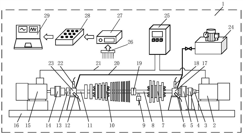
[0024] figure 1 It is a schematic diagram of the overall structure of an embodiment of the circumferential tie rod rotor experimental system. The circumferential tie rod rotor experimental system 1 mainly includes a support base 16, a driving motor 2, an experimental rotor, a generator 15, a lubricating oil tank 24, a frequency converter 25 and data acquisition and Processing system: the experimental rotor includes an experimental rotor turbine shaft section 7 and an experimental rotor compressor shaft section 10; one end of the experimental rotor turbine shaft section passes through the first rolling bearing 17 and the first elastic coupling 5 in turn to drive The output shaft of the motor 2 is connected; one end of the experimental rotor compressor shaft section 10 is co...


PUM


Abstract

The invention discloses a circumferential pull rod rotor experiment system. The experiment system comprises a supporting base, a driving motor, an experimental rotor, a generator, a lubricating oil tank, a frequency converter and a data acquisition and processing system, and the experimental rotor comprises an experimental rotor turbine shaft section and an experimental rotor compressor shaft section, and the two sections are connected through a coupler to form an integral rotor detachable structure. The system has relatively high experimental flexibility, and can be used for researching the dynamic characteristics of the rotor in different contact states; dynamic experiment of the whole rotor can be carried out through the intermediate coupler, and the part-level dynamic experiment of the rotor can also be carried out; by reasonably designing the sizes and the proportions of the rotor and a wheel disc, the wheel disc can effectively work between a second-order critical rotating speed and a third-order critical rotating speed which are consistent with those of an actual gas turbine rotor, and the defect that most experiment tables cannot measure the third-order critical rotating speed due to the scaling effect is overcome; and the system has high experiment and application values for simulating the operation characteristics of the rotor in different wheel disc contact states.

Description

technical field [0001] The invention relates to the technical field of rotating machinery experiment systems, in particular to a dynamic experiment system for a circumferential tie rod rotor. Background technique [0002] Heavy-duty gas turbines are widely used in power generation. Among them, the circumferential tie-rod rotor system is one of the main rotor structures of heavy-duty gas turbines, and its dynamic characteristics have an important impact on the safety and reliability of the entire heavy-duty gas turbine. Compared with the integrally welded rotor, since the compressor wheel and the turbine wheel of the circumferential tie-rod rotor system are preloaded through the circumferential tie rods, the contact effect of the contact interface will generate additional contact stiffness, which will affect the inherent stiffness of the entire rotor. Frequency, critical speed and vibration characteristics. Therefore, the experimental research on the dynamic characteristics...

Claims


Application Information

Patent Timeline
Patent Type & Authority Applications(China)
IPC IPC(8): G01M13/00G09B23/06
CPCG01M13/00G09B23/06
Inventor 刘超谢文振蒋东翔
Owner TSINGHUA UNIV
Why Eureka
Try Eureka