

Optical image capturing system, image capturing module and electronic device
An optical imaging system and optical axis technology, applied in optics, optical components, instruments, etc., can solve the problems of difficult to meet high-resolution large-scale use, high processing cost, complex structure to improve resolution, and reduce ghosting. risk, reduce processing difficulty, and improve the effect of wide-angle
- Summary
- Abstract
- Description
- Claims
- Application Information
AI Technical Summary
Problems solved by technology
Method used
Image

Examples
no. 1 example
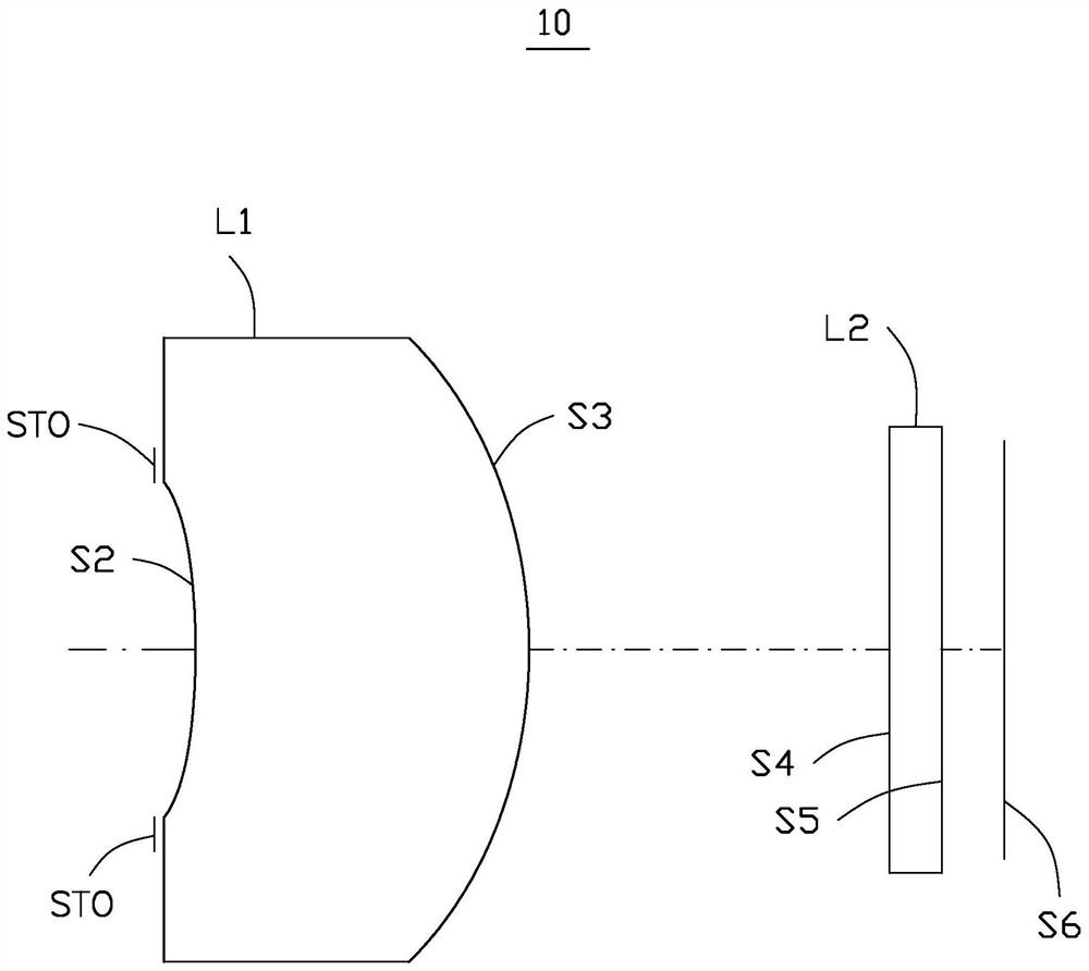
[0114] Please refer to figure 1 The optical imaging system 10 of the first embodiment includes a stop STO, a lens L1 with positive refractive power, and a protective plate L2 sequentially from the object side to the image side.
[0115] Wherein, the object side S2 of the lens L1 is concave at the near optical axis, and the image side S3 is convex at the near optical axis.
[0116]The reference wavelength of the focal length in the first embodiment is 10000 nm, the reference wavelength of the material refractive index and Abbe number is 587.56 nm, and the optical imaging system 10 in the first embodiment satisfies the conditions in Table 1 below. Wherein, the Y radius in this embodiment is the curvature radius of the lens L1 at the near optical axis.
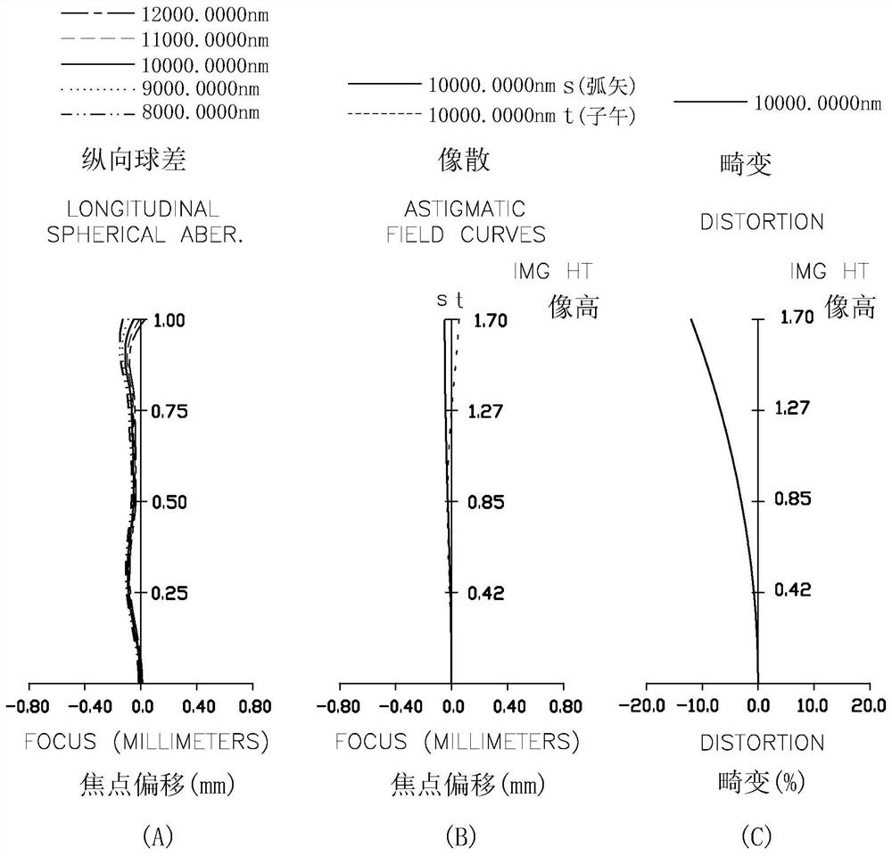
[0117] Table 1
[0118]
[0119] It should be noted that f is the effective focal length of the optical imaging system 10, FNO is the aperture number of the optical imaging system 10, FOV is the maximum field of view of the ...
no. 2 example
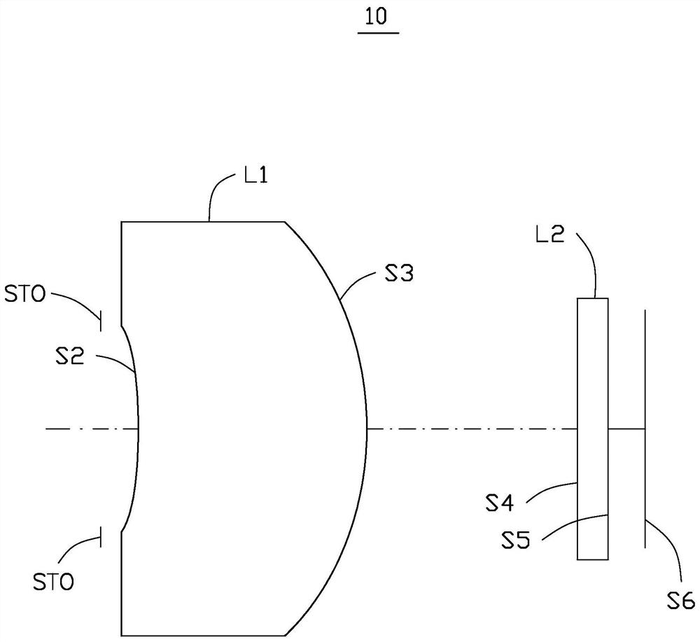
[0128] Please refer to image 3 , the optical imaging system 10 of the second embodiment includes a diaphragm STO, a lens L1 with positive refractive power, and a protective plate L2 sequentially from the object side to the image side.
[0129] Wherein, the object side S2 of the lens L1 is concave at the near optical axis, and the image side S3 is convex at the near optical axis.
[0130] The reference wavelength of focal length in the second embodiment is 10000 nm, the reference wavelength of material refractive index and Abbe number is 587.56 nm, and the optical imaging system 10 in the second embodiment satisfies the conditions in Table 3 below. Wherein, the Y radius in this embodiment is the curvature radius of the lens L1 at the near optical axis.
[0131] table 3
[0132]
[0133] It should be noted that f is the effective focal length of the optical imaging system 10, FNO is the aperture number of the optical imaging system 10, FOV is the maximum field of view of t...
no. 3 example
[0142] Please refer to Figure 5 The optical imaging system 10 of the third embodiment includes a stop STO, a lens L1 with positive refractive power, and a protective plate L2 sequentially from the object side to the image side.
[0143] Wherein, the object side S2 of the lens L1 is concave at the near optical axis, and the image side S3 is convex at the near optical axis.
[0144] The reference wavelength of focal length in the third embodiment is 10000 nm, the reference wavelength of material refractive index and Abbe number is 587.56 nm, and the optical imaging system 10 in the third embodiment satisfies the conditions in Table 5 below. Wherein, the Y radius in this embodiment is the curvature radius of the lens L1 at the near optical axis.
[0145] table 5
[0146]
[0147] It should be noted that f is the effective focal length of the optical imaging system 10, FNO is the aperture number of the optical imaging system 10, FOV is the maximum field of view of the optica...
PUM
 Abstract
Description
Claims
Application Information