Aluminum alloy surface spraying device
A technology of aluminum alloy surface and spraying device, which is applied in the direction of spraying device, spray booth, etc., can solve the problems of automatic spraying of aluminum boxes, etc., and achieve the effect of reducing floor space and realizing automation
- Summary
- Abstract
- Description
- Claims
- Application Information
AI Technical Summary
Problems solved by technology
Method used
Image

Examples
specific Embodiment approach 1
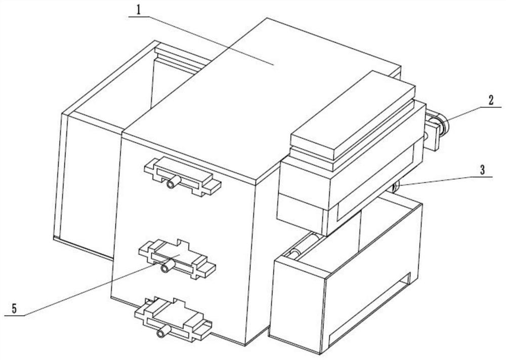
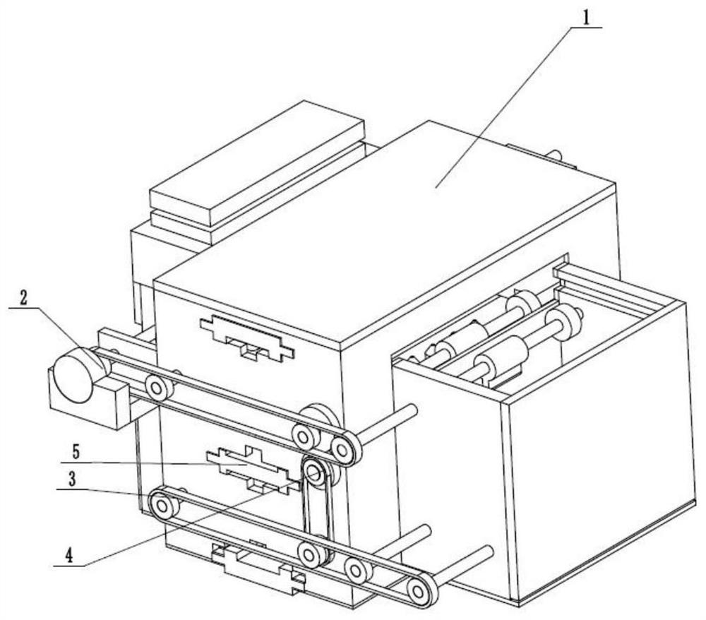
[0028] Such as Figure 1 to Figure 9 As shown, an aluminum alloy surface spraying device includes a carrying spraying box 1, an upper transport drive 2, a lower transport drive 3, a reverse connection transfer device 4 and three spraying sliders 5, and the upper transport drive 2 is rotatably connected In the carrying spray box 1, the upper transport driver 2 is engaged with the reverse connection transfer device 4, the reverse connection transfer device 4 is engaged with the lower transport drive 3, and the lower transport drive 3 is rotatably connected in the transfer spray box 1, three The spraying slider 5 is evenly slidably connected in the carrying spraying box 1 . Stack the aluminum alloy plates of the same specifications to be sprayed on the carrying spray box 1, and gradually add the aluminum alloy plates to the carrying spray box 1 through the drive of the upper transport drive 2, and the three spraying sliders 5 are all connected The spraying pipeline with pressure...
specific Embodiment approach 2
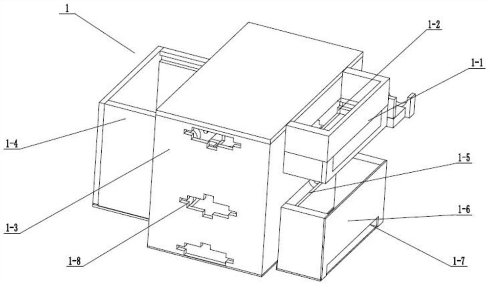
[0030] Such as Figure 1 to Figure 9As shown, this embodiment further explains the first embodiment. The carrying spray box 1 includes an aluminum alloy stacked push frame 1-1, a push slot 1-2, a spray box 1-3, and an aluminum alloy flip frame 1-4. , discharge slot 1-5, recovery stacking frame 1-6, recovery slot 1-7, three spraying adjustment sliding slots 1-8, flip push slot 1-9 and flip push slot 1-10, aluminum alloy stack push frame 1 -1 is fixedly connected to the upper side of the right end of the spraying box 1-3, and the push-in groove 1-2 is set on the upper side of the right end of the spraying box 1-3 and communicates with the aluminum alloy stacking pushing frame 1-1, and the aluminum alloy turning frame 1-4 It is fixedly connected to the left end of the spraying box 1-3, and the turning and pushing groove 1-9 and the turning pushing groove 1-10 are arranged on the left end of the spraying box 1-3, and the turning and pushing groove 1-9 and the turning pushing groov...
specific Embodiment approach 3
[0032] Such as Figure 1 to Figure 9 As shown, this embodiment further explains the second embodiment. The upper transport driver 2 includes a drive motor 2-1, a main push shaft 2-2, a right connecting shaft 2-3, a left connecting turning shaft 2-4, and a turning shaft 2-4. Propel rotating shaft 2-5, advance rubber wheel 2-6 and two overturning cams 2-7, drive motor 2-1 is fixedly connected on the right side of spraying box 1-3 front end by motor holder, main pushes rotating shaft 2-2 through joint The shaft is connected to the transmission shaft of the drive motor 2-1, the main pusher shaft 2-2 is rotationally connected in the aluminum alloy stacked push frame 1-1, the main pusher shaft 2-2 is connected to the right shaft 2-3 through the synchronous belt transmission, and the left side is turned over The rotating shaft 2-4 and the turning and propulsion rotating shaft 2-5, the right connecting rotating shaft 2-3 and the left connecting turning rotating shaft 2-4 are all conne...
PUM
 Abstract
Description
Claims
Application Information
 - R&D Engineer
- R&D Manager
- IP Professional
- Industry Leading Data Capabilities
- Powerful AI technology
- Patent DNA Extraction
Browse by: Latest US Patents, China's latest patents, Technical Efficacy Thesaurus, Application Domain, Technology Topic.
© 2024 PatSnap. All rights reserved.Legal|Privacy policy|Modern Slavery Act Transparency Statement|Sitemap