
T-shaped beam prefabricating equipment suitable for large longitudinal slope beam field

A technology of equipment and wing plates, applied in the field of T-beam prefabrication equipment, can solve problems such as poor compatibility and non-compliance

Active Publication Date: 2021-04-27
中电建路桥集团有限公司
View PDF8 Cites 0 Cited by
  • Summary
  • Abstract
  • Description
  • Claims
  • Application Information

AI Technical Summary

Problems solved by technology

[0004] With the continuous development of my country's economy, more and more highways are built in mountainous areas, and it is inevitable to encounter harsh terrain conditions such as large longitudinal slopes when site selection and site planning for prefabricated beam yards. According to the research, the current T-beam construction technology often uses ordinary horizontal prefabricated beam field molds to prefabricate T-beams with small longitudinal slopes or no longitudinal slopes on sites close to the horizontal plane. However, it is very rare, which seriously does not meet the development needs of my country's current bridges, roads and other transportation facilities. As a result, when the ordinary horizontal prefabricated beam field mold is used for prefabrication in the large longitudinal slope prefabricated beam field, the mold is at a large angle. The height of the T-shaped beam can only be met by artificially increasing the height of the mold on the lower side of the longitudinal slope. This method is a temporary modification measure, and the mold made can only be used for A beam field with a single slope cannot be used again for beam fields with other longitudinal slopes, so the compatibility is poor

Method used


Image

  • T-shaped beam prefabricating equipment suitable for large longitudinal slope beam field
  • T-shaped beam prefabricating equipment suitable for large longitudinal slope beam field
  • T-shaped beam prefabricating equipment suitable for large longitudinal slope beam field

Examples


Embodiment Construction

[0021] In the present invention, the terms "arranged", "provided", and "connected" should be interpreted broadly. For example, it may be a fixed connection, a detachable connection, or an integral structure; it may be a mechanical connection or an electrical connection; it may be a direct connection or an indirect connection through an intermediary; internal connectivity. Those of ordinary skill in the art can understand the specific meanings of the above terms in the present invention according to specific situations.

[0022] The terms "center", "longitudinal", "transverse", "length", "width", "thickness", "top", "bottom", "front", "rear", "left", "right", " Vertical", "horizontal", "top", "bottom", "inner", "outer", "clockwise", "counterclockwise", "axial", "radial", "circumferential", etc. The orientation or positional relationship is based on the orientation or positional relationship shown in the drawings, and is only for the convenience of describing the application a...


PUM


Abstract

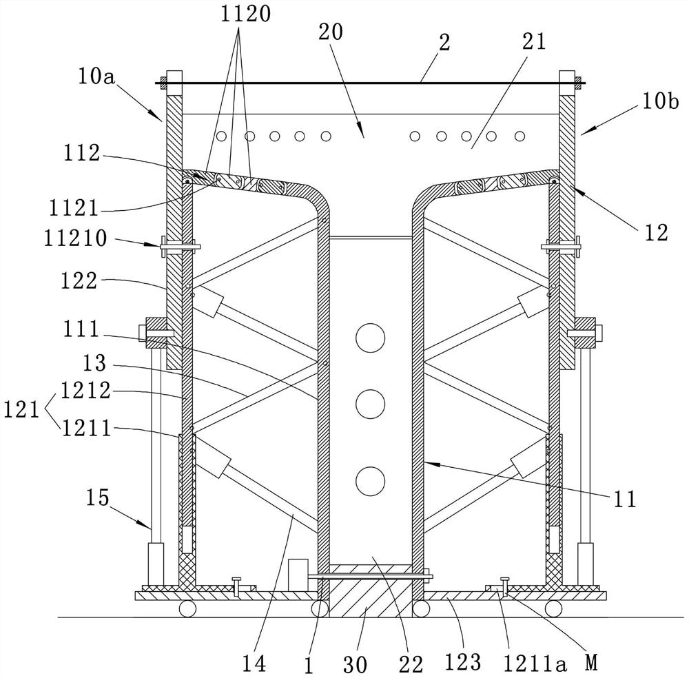
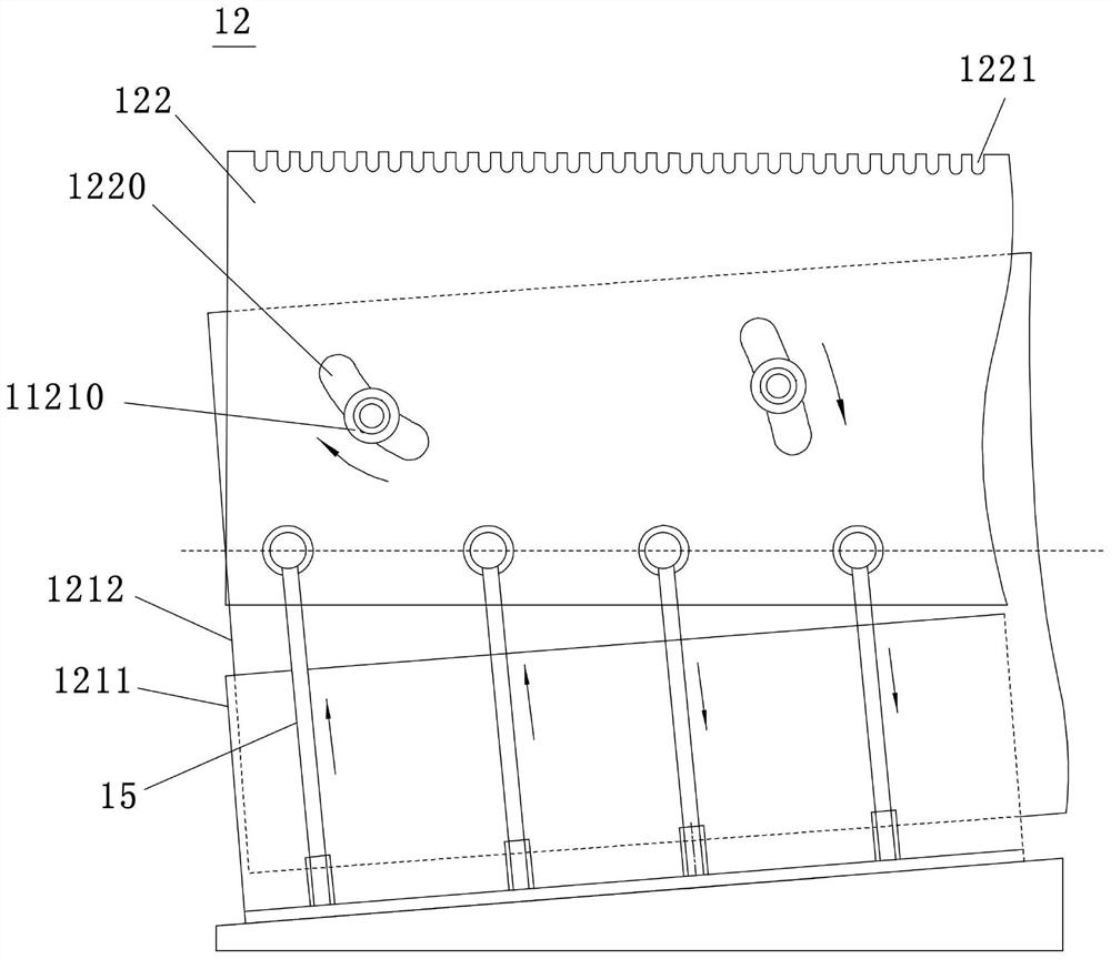
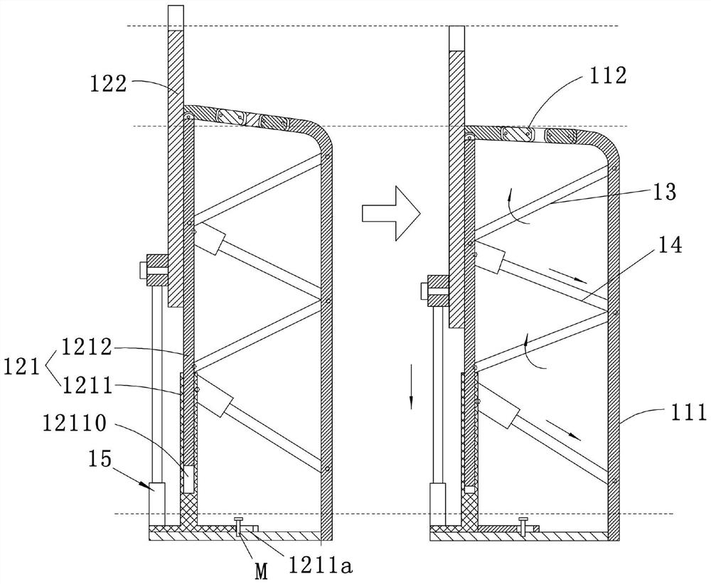
The invention discloses a T-shaped beam prefabricating equipment suitable for a large longitudinal slope beam field. A side formwork of the T-shaped beam prefabricating equipment comprises a left formwork body and a right formwork body, wherein the left formwork body and the right formwork body each comprise an inner formwork body and an outer formwork body, each inner formwork body comprises a vertical plate right opposite to the right formwork body on the opposite side and a wing plate connected to the top of the vertical plate and extending outwards and obliquely upwards, each outer formwork body comprises an outer lower formwork body and an outer upper formwork body, the outer lower formwork body is arranged below the wing plate, the lower portion of the outer upper formwork body is rotatably attached to the outer side surface of the outer lower formwork body, the upper portion of the outer upper formwork body is higher than the wing plate, and the inner side face of the outer upper formwork body abuts against the wing plate to define a prefabricated space of a T-shaped beam. According to the equipment, the outer formwork body, of the side formwork are arranged into a plurality of separated parts, the outer upper formwork body is rotated relative to the outer lower formwork body, and a height and an inclination angle of the outer upper formwork body can be adjusted according to the longitudinal slope adaptability of the beam field, so that the equipment can adapt to various longitudinal slope beam fields, and the wing plates on the two sides of the T-shaped beam are prevented from leaking slurry in a prefabricating process. Meanwhile, the cross slope of the T-shaped beam can be adjusted by adjusting the extending angles of the wing plates, and different prefabrication requirements are met.

Description

technical field [0001] The invention relates to the technical field of road and bridge engineering, in particular to a T-shaped beam prefabrication equipment suitable for a large longitudinal slope beam field. Background technique [0002] T-shaped beam (T-shaped beam, also known as T-beam) refers to the beam with a T-shaped cross-section. The part on both sides of the T-shaped beam is called the flange, and the middle part is called the beam rib. The compression area uses pressure-resistant concrete to make the flange plate and doubles as the bridge deck; the tension area uses steel bars or prestressed steel bars to bear the tension. The prestressed concrete T-beam bridge has simple structure, clear force, saves materials, and is easy to erect and install. With the advantages of convenience and large spanning ability, it is widely used in road construction and bridge construction in our country, and the amount of use is very large. [0003] my country has a large range of ...

Claims


Application Information

Patent Timeline
IPC IPC(8): B28B7/22B28B7/02
CPCB28B7/22B28B7/02
Inventor 傅利荣杨柳廖名举韩晓凌
Owner 中电建路桥集团有限公司
Learn More