Paper treatment device
A paper processing device and paper technology, applied in book binding, book binding flattening machine, printing, etc., can solve the problems of large configuration space, kicking out, unable to flatten paper, etc., and achieve the effect of reducing space
- Summary
- Abstract
- Description
- Claims
- Application Information
AI Technical Summary
Problems solved by technology
Method used
Image

Examples
Embodiment Construction
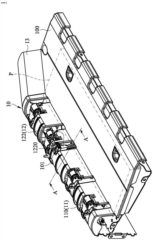
[0062] see Figure 1 to Figure 2 , figure 1 It is a schematic diagram of the appearance structure of a paper processing device according to an embodiment of the present invention. figure 2 along figure 1 Schematic cross-sectional view of line AA shown. The paper processing device 1 of this embodiment is, for example, arranged above or on both sides of a printing device (not shown). Binding or punching, etc. Such as figure 1 and figure 2 As shown, the paper processing device 1 of this embodiment includes a housing 10 , a transport roller set 11 and a paper pressing device 12 . The casing 10 includes a paper loading platform 100 extending outward. The conveying roller set 11 is disposed on the casing 100 and is used for conveying the papers P from the printing device to the paper placing platform 100 . The paper pressing device 12 is disposed below the housing 10 , and the paper pressing device 12 includes a support frame 121 , a paper pressing rod 122 , a driving asse...
PUM
 Abstract
Description
Claims
Application Information
PatSnap Eureka turns technology decisions into work you can execute. Powered by our Innovation Knowledge Graph, it runs expert workflows across engineering, life sciences, materials and intellectual property. Get your review-ready output in minutes.


