
Incubator for in-vitro heart experiment

An experimental, incubator technology, applied in thermal insulation containers, applications, household appliances, etc., can solve the problems of damage accuracy, no heart insulation tank, dry heart surface, etc., to ensure stability, facilitate experimental operation, and ensure stability sexual effect

Active Publication Date: 2021-04-27
CAPITAL UNIVERSITY OF MEDICAL SCIENCES
View PDF10 Cites 0 Cited by
  • Summary
  • Abstract
  • Description
  • Claims
  • Application Information

AI Technical Summary

Problems solved by technology

The isolated heart perfusion method has been widely used in physiological, pathophysiological and pharmacological research. So far, people are still using this important technology in the cardiovascular field. However, in the process of establishing the isolated heart perfusion model, various operations Damage to the myocardium, the huge difference between the external environment and the internal environment, and the lack of regulation of normal neurohumoral fluids will inevitably damage the myocardial tissue and affect the accuracy of the experiment, or the implementation of certain operations is limited due to the narrow space
[0003] The existing widely used cardiac perfusion system generally only heats the perfusate, without a heart warming tank, resulting in the heart being exposed to the air, which is not conducive to maintaining the temperature of the heart, and it is easy to cause the surface of the heart to dry out
Or use a beaker-shaped double-layer heat preservation tank during the experiment, but the volume is too small, which is not conducive to placing various recording electrodes, and in the process of experimental operation, it is generally necessary to remove the heat preservation tank, so that the heart cannot be kept in good condition. physiological state

Method used


Image

  • Incubator for in-vitro heart experiment
  • Incubator for in-vitro heart experiment
  • Incubator for in-vitro heart experiment

Examples


Embodiment Construction

[0026] The following will clearly and completely describe the technical solutions in the embodiments of the present invention in conjunction with the accompanying drawings. Obviously, the described embodiments are only some of the embodiments of the present invention, not all of them. Based on the embodiments of the present invention, all other embodiments obtained by persons of ordinary skill in the art without making creative efforts belong to the protection scope of the present invention.

[0027] In the description of this patent, it is to be understood that the terms "center", "upper", "lower", "front", "rear", "left", "right", "vertical", "horizontal", The orientation or positional relationship indicated by "top", "bottom", "inner", "outer", etc. is based on the orientation or positional relationship shown in the drawings, and is only for the convenience of describing this patent and simplifying the description, rather than indicating or implying References to devices or...


PUM


Abstract

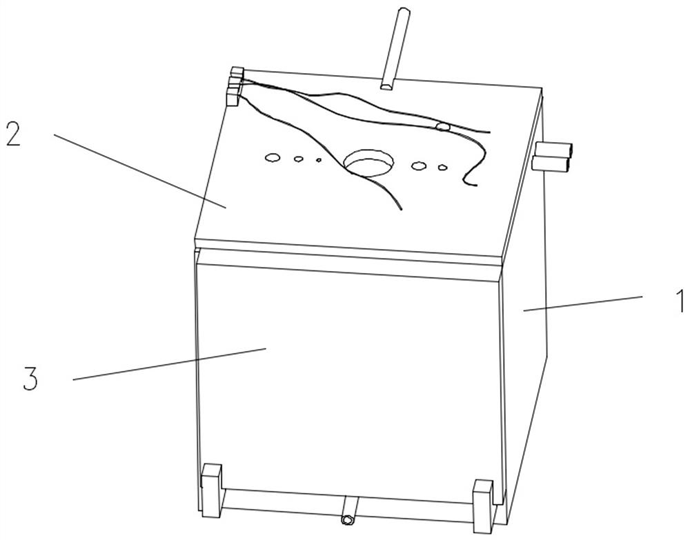
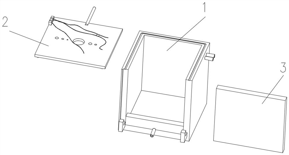
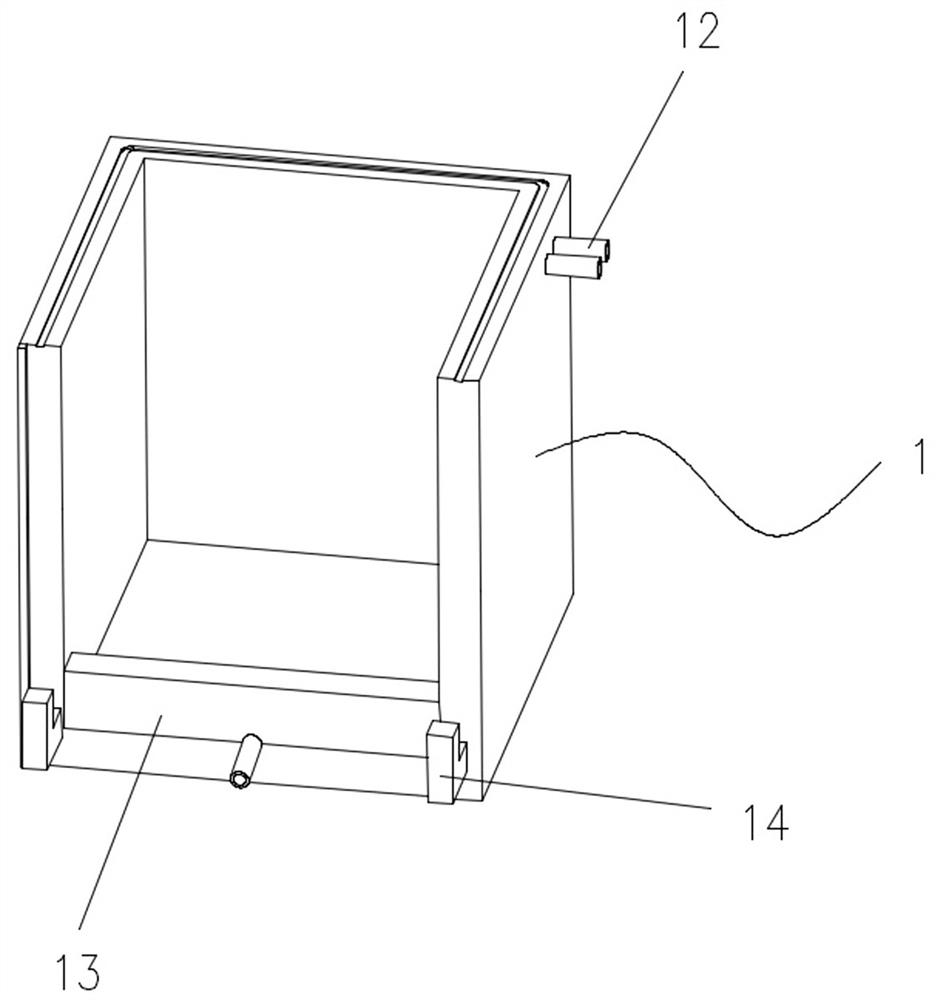
The invention discloses an incubator for an in-vitro heart experiment. The incubator comprises a box body, a top cover and a front cover, wherein the top cover is detachably connected to the top of the box body, and the front cover is detachably connected to the front side of the box body. The box body comprises side plates and a bottom plate, wherein inner cavities are formed in the side plates and the bottom plate correspondingly, the inner cavities in the side plates and the inner cavity in the bottom plate are communicated with each other to form an integrated closed heat preservation cavity, heat preservation liquid is arranged in the heat preservation cavity, and two liquid passing pipes communicated with the heat preservation cavity are arranged on the side plates and are served as an inlet and an outlet for heat-insulating liquid respectively. The heat preservation cavity is formed in the box body, the heat preservation liquid is uninterruptedly circulated in the heat preservation cavity, a constant-temperature environment is created in the box body, a perfusion device is matched to enable an isolated heart to be in a constant-temperature state all the time in the experiment process, and the accuracy of the experiment result is guaranteed.

Description

technical field [0001] The invention relates to the technical field of experimental equipment, in particular to an incubator for isolated heart experiments. Background technique [0002] The mammalian isolated heart perfusion model was established in 1895 by Oscar Langendorff. The isolated heart perfusion method has been widely used in physiological, pathophysiological and pharmacological research. So far, people are still using this important technology in the cardiovascular field. However, in the process of establishing the isolated heart perfusion model, various operations The damage to the myocardium, the huge difference between the external environment and the internal environment, and the lack of normal neurohumoral regulation will inevitably damage the myocardial tissue and affect the accuracy of the experiment, or restrict the implementation of certain operations due to the narrow space. [0003] The existing widely used cardiac perfusion system generally only heats...

Claims


Application Information

Patent Timeline
IPC IPC(8): B65D25/02B65D43/02B65D81/22B65D81/38B65D85/50
CPCB65D25/02B65D43/02B65D81/22B65D81/382B65D85/50
Inventor 刘萍王伟黄海霞魏华辛方任杰程塬文新鑫赵凤张进
Owner CAPITAL UNIVERSITY OF MEDICAL SCIENCES
Learn More