Working method of sleeve workpiece feeding mechanism

A technology of pushing mechanism and sleeve, which is applied to conveyors, conveyor objects, rotary conveyors, etc., can solve the problems of sleeve workpieces not being able to work, and the sleeve workpieces being difficult to translate, push, feed, and process.

Inactive Publication Date: 2021-04-27
龚文科
View PDF0 Cites 2 Cited by
  • Summary
  • Abstract
  • Description
  • Claims
  • Application Information

AI Technical Summary

Problems solved by technology

During the production and processing of sleeve workpieces, the sleeve workpieces that have been processed by the previous process need to be loaded one by one to enable the processing of the subsequent process. The existing sleeve workpieces are processed after the previous process. , in order to continue the production and processing of the sleeve workpieces, the existing method is to manually feed the sleeve workpieces one by one, the labor intensity of the workers is relatively high, and the feeding efficiency of the sleeve workpieces is low, making it difficult to meet large-scale According to the needs of the production and processing of sleeve workpieces, the transfer of the existing sleeve workpieces is mainly to place the sleeve workpieces on the turntable and rely on the horizontal rotation of the turntable to realize the smooth transfer of the sleeve workpieces. The process of pushing the cylinder workpiece to the turntable is usually carried out when the turntable is at a standstill, that is, the turntable generally rotates intermittently. The existing mechanism of intermittently driving the turntable is complicated and cumbersome to operate, and it is difficult to accurately stop the turntable at the required position. , which makes it difficult for the sleeve workpiece to be accurately translated and pushed, which affects the continuous feeding of the sleeve workpiece. It is difficult for the existing sleeve workpiece transfer mechanism to transfer the sleeve workpiece during the transfer process. The convenient clamping and fixing during the transfer process makes the sleeve workpiece easy to fall off during the transfer process, and the existing transfer mechanism needs to install an additional manipulator to remove the sleeve workpiece after transferring the sleeve workpiece to the desired position. In the process of grabbing and translating the sleeve workpiece, some manipulators often cause the sleeve workpiece to fall off due to poor grasping during the process of grabbing the sleeve workpiece, resulting in the sleeve workpiece not being able to be normally carried out in subsequent processes processing, so that the efficiency and quality of sleeve workpiece processing cannot be guaranteed, and in the process of using the manipulator to grab the sleeve workpiece, the manipulator needs multiple driving mechanisms to drive continuously and independently, the driving energy consumption is high, and The multi-drive mechanism is also prone to failure, and it is difficult to run stably for a long period of time, which reduces the efficiency and quality of continuous transfer processing of sleeve workpieces, and cannot meet the needs of processing and use.

Method used


Image

  • Working method of sleeve workpiece feeding mechanism
  • Working method of sleeve workpiece feeding mechanism
  • Working method of sleeve workpiece feeding mechanism

Examples


Embodiment Construction

[0017] In order to further describe the present invention, the specific implementation of a sleeve workpiece feeding mechanism will be further described below in conjunction with the accompanying drawings. The following examples are explanations of the present invention and the present invention is not limited to the following examples.

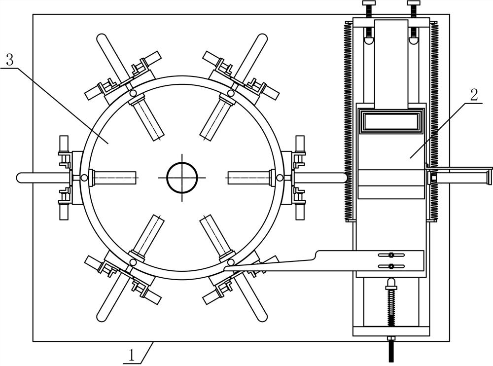
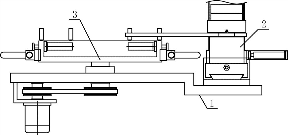
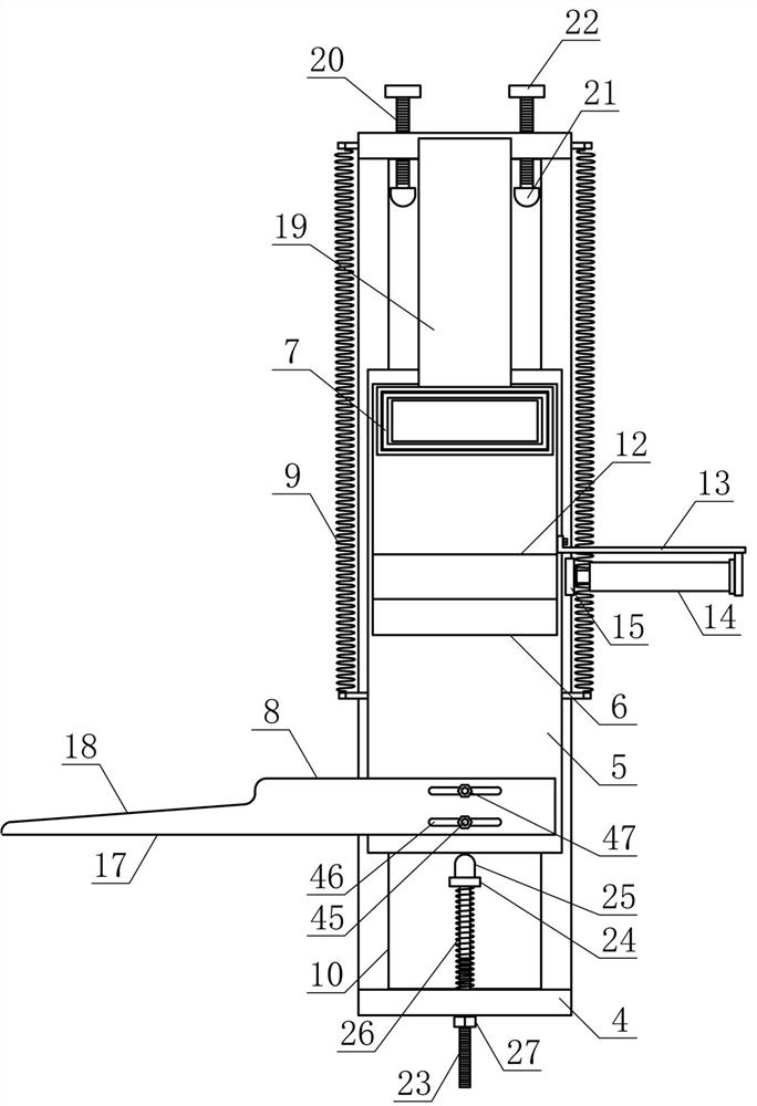
[0018] Such as figure 1 , figure 2 As shown, a sleeve workpiece loading mechanism of the present invention includes a loading base 1, a pushing mechanism 2 and a transfer mechanism 3, and the pushing mechanism 2 and the transferring mechanism 3 are horizontally and horizontally fixedly arranged on the loading base 1 in sequence. side. Such as image 3 , Figure 4 with Figure 5As shown, the pusher mechanism 2 of the present invention includes a translation support 4, a reciprocating guide plate 5, a material transfer connecting plate 6, a guide barrel material tube 7, a synchronous connecting plate 8 and a reset tension spring 9, and the...


PUM


Abstract

The invention discloses a working method of a sleeve workpiece feeding mechanism, and belongs to the field of workpiece machining and conveying mechanical equipment. A pushing mechanism and a transferring mechanism are sequentially, horizontally and fixedly arranged on the upper side of a feeding base in the horizontal direction, a reciprocating guide plate is arranged on a translation guide strip of a translation support in a sliding mode in the horizontal direction, a translation push plate which is of a circular structure and is matched with a bearing barrel material channel is vertically and fixedly arranged at the output end of a pushing air cylinder, reset tension springs are horizontally arranged on the two sides of the reciprocating guide plate and the ends of guide pipes of the translation support, the middle of the lower side of a circular transferring plate is fixedly connected with the end of the upper side of a feeding rotating shaft, and a plurality of bearing barrel mechanisms are sequentially and evenly arranged on the circular transferring plate in the radial direction of the circular transferring plate. The structural design is reasonable, sleeve workpieces can be horizontally moved, pushed and accurately placed one by one, stable and efficient transferring, feeding and machining of the sleeve workpieces are achieved, the automation degree of workpiece feeding is improved, and the requirements of production and use are met.

Description

technical field [0001] The invention belongs to the field of workpiece processing and conveying machinery, and in particular relates to a working method of a sleeve workpiece feeding mechanism, which is mainly applied to the continuous transfer processing of sleeve workpieces one by one. Background technique [0002] The sleeve workpiece refers to the workpiece with a cylindrical structure. There are many types of sleeve workpieces. Different sleeve workpieces use different materials. The quality of the material directly determines the quality of the sleeve workpiece. The sleeve workpiece is a construction and mechanical The necessary materials for the equipment, the sleeve workpiece is a general term for the parts that play the role of connection, control, direction change, shunt, seal, support, etc. in the mechanical system. During the production and processing of sleeve workpieces, the sleeve workpieces that have been processed by the previous process need to be loaded on...

Claims


Application Information

Patent Timeline
Patent Type & Authority Applications(China)
IPC IPC(8): B65G47/82B65G29/00
CPCB65G29/00B65G47/04B65G47/82
Inventor 龚文科
Owner 龚文科
Why Eureka
Try Eureka