Valve structure and one-way valve
A technology of valve and connection structure, which is applied in the direction of the valve housing structure, the parts in contact between the valve element and the valve seat, and the control valve. It can solve the problems of high damage rate and ineffective disconnection of the valve, so as to reduce damage rate, Achieve effective disconnection and reduce damage
- Summary
- Abstract
- Description
- Claims
- Application Information
AI Technical Summary
Problems solved by technology
Method used
Image

Examples
Embodiment 1
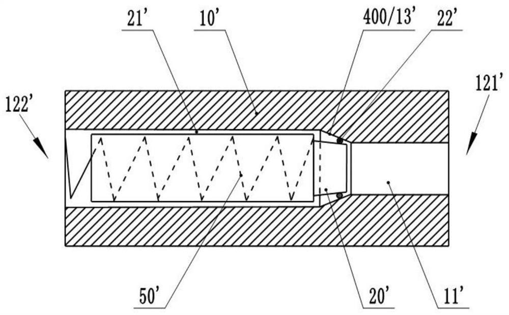
[0109] Such as image 3 and Figure 6As shown, the present invention provides a valve structure, comprising: a valve body 10, which is provided with a fluid channel 11; a valve column 20, which is movably connected in the fluid channel 11; the valve column 20 is provided with an annular protrusion 30, and the valve column The inner wall of the body 10 is provided with an abutting structure 40 that matches the annular protrusion 30, and the valve column 20 can move relative to the valve body 10 until the annular protrusion 30 abuts against the abutting structure 40, so that the fluid passage 11 is closed. . A groove 31 is formed on the end surface of the spool 20 , and an annular protrusion 30 is formed on an edge of the groove 31 .
[0110] The valve structure cooperates with the abutting structure 40 on the valve body 10 through the annular protrusion 30 to realize the sealing between the valve column 20 and the valve body 10 and the disconnection of the fluid channel 11 . ...
Embodiment 2
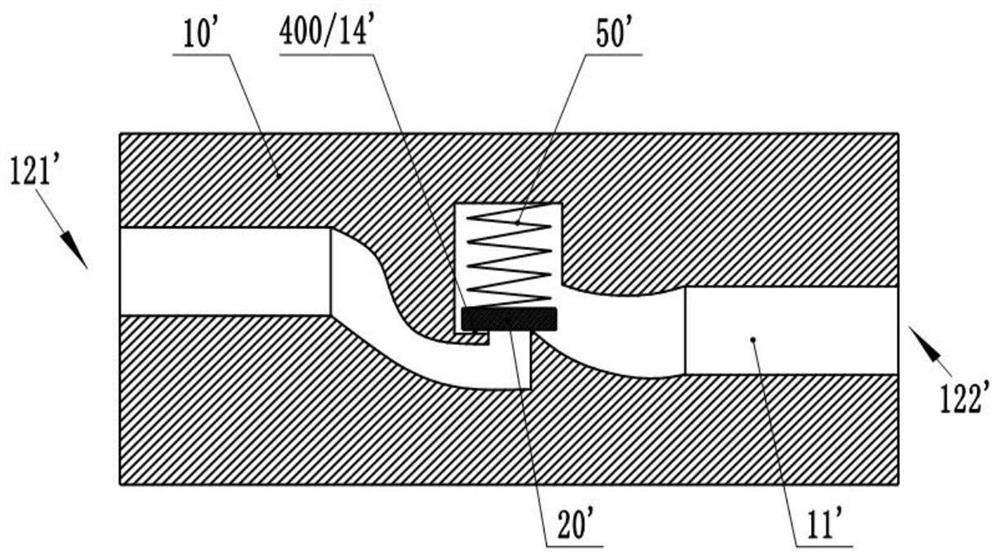
[0134] Such as image 3 and Figure 6 As shown, the present invention provides a valve structure, comprising: a valve body 10, which is provided with a fluid channel 11; a valve column 20, which is movably connected in the fluid channel 11; With the first matching structure 400, the valve column 20 can move relative to the valve body 10 to abut against the first matching structure 400, so that the fluid channel 11 is closed; the fluid channel 11 is provided with a pore structure column 60, and the pore structure column The body 60 is located on a side of the first matching structure 400 away from the spool 20 .
[0135] The airflow usually contains solid particles, and the solid particles carried by the high-speed airflow will cause relatively strong damage to the wall. In the valve structure provided by the present invention, the pore structure cylinder 60 can block solid particles on the one hand, and on the other hand, high-speed gas flows through the complex pores in the...
Embodiment 3
[0144] Such as image 3 , Figure 6 and Figure 7 As shown, the present invention provides a valve structure, comprising: a valve body 10, which is provided with a fluid channel 11; a valve column 20, which is movably connected in the fluid channel 11; the valve column 20 is provided with an annular protrusion 30, and the valve column The inner wall of the body 10 is provided with an abutting structure 40 that matches the annular protrusion 30, and the valve column 20 can move relative to the valve body 10 until the annular protrusion 30 abuts against the abutting structure 40, so that the fluid passage 11 is closed. . A groove 31 is formed on the end surface of the spool 20 , and an annular protrusion 30 is formed on an edge of the groove 31 . A pore structure column 60 is disposed in the fluid channel 11 , and the pore structure column 60 is located on a side of the abutting structure 40 away from the valve column 20 .
[0145] The valve structure has the following advan...
PUM
| Property | Measurement | Unit |
|---|---|---|
| Thickness | aaaaa | aaaaa |
Abstract
Description
Claims
Application Information
 - Generate Ideas
- Intellectual Property
- Life Sciences
- Materials
- Tech Scout
- Unparalleled Data Quality
- Higher Quality Content
- 60% Fewer Hallucinations
Browse by: Latest US Patents, China's latest patents, Technical Efficacy Thesaurus, Application Domain, Technology Topic, Popular Technical Reports.
© 2025 PatSnap. All rights reserved.Legal|Privacy policy|Modern Slavery Act Transparency Statement|Sitemap|About US| Contact US: help@patsnap.com