A Large Range Differential Resistive Strain Gauge

A differential resistance and strain gauge technology, applied in the field of strain gauges, can solve the problems of sacrificing the accuracy of instrument parameters, different parameters, different initial prestresses, etc., to achieve a convenient degree of improvement, completely consistent deformation state, and large strain output range. Effect

Active Publication Date: 2022-08-05
STATE GRID ELECTRIC POWER RES INST +3
View PDF8 Cites 0 Cited by
  • Summary
  • Abstract
  • Description
  • Claims
  • Application Information

AI Technical Summary

Problems solved by technology

[0004] The existing differential resistance strain gauge has the following disadvantages: the differential sensing structure such as figure 2 As shown, the differential steel wire is an inner and outer ring structure. To ensure that the length of the inner and outer ring steel wires is basically the same, the number of winding turns of the inner and outer ring steel wires must be unequal. Obviously, when the structure has a certain displacement, the deformation of the inner and outer ring steel wires is different. Yes, and in most cases, in order to meet the different tension and compression states of the actual application scene, the initial prestress of the two groups of steel wires is different
It is not difficult to see that in the same measurement environment, when the temperature change is the main factor, the temperature influence coefficient of the differential steel wire resistance is not the same, and the use of the same temperature influence coefficient will inevitably sacrifice the accuracy of the instrument parameters

Method used


Image

  • A Large Range Differential Resistive Strain Gauge
  • A Large Range Differential Resistive Strain Gauge
  • A Large Range Differential Resistive Strain Gauge

Examples


Embodiment Construction

[0025] The following combined with the attachment is further described by the present invention. The following examples are only used to explain the technical solutions of the present invention more clearly, and cannot limit the protection scope of the present invention based on this.

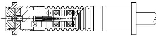
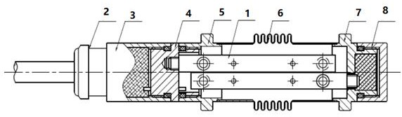
[0026] like image 3 It shows that a large number of differential dynamic resistance types include the end components connected in turn, the protective shell, the tail component, and the differential dynamic response structure 1. Differential sensing structure 1 is fixed in the protective shell, and the front end and back -end of the differential sensing structure 1 are connected to the end component and the tail component, respectively.

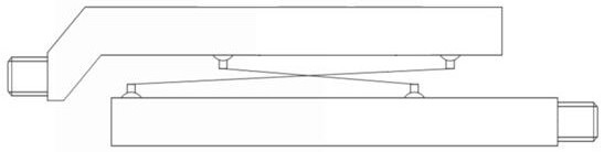
[0027] like Figure 4 Show, differential sensor structure 1 includes front differential steel wire 11, rear differential steel wire 12, upper structural part 9 and lower structural parts 10.

[0028] Both the upper structural part 9 and the lower structural parts 1...


PUM


Abstract

The present invention disclosed a large number of different dynamic resistance -type strain meters, including the end components that are connected in turn, the protective shell of the built -in differential dynamic structure, and the tail component.Connecting the lower structures connected to the tail component, the upper structure and lower structural parts set the structure component group in order from top to bottom.The dynamic steel wire is located on the front and back of the structural parts, respectively, and is arranged in X -symmetrical. The two ends of the front differential steel wire are fixed with the front side of the upper structure and the lower part of the lower structure.The rear side of the lower form component is fixed, and the length of the upper structural parts and the lower structural parts is greater than the marking distance of the large amount of motion resistance.The parameters of the present invention are accurate, the range of range is easy to regulate, the differentiality of the differential sensor structure, and the existing output range of the full range.

Description

Technical field [0001] The present invention involves a large amount of motion -resistant resistance, which belongs to the field of strain meter technology. Background technique [0002] Differential resistance -resistant strain instruments have simple and long -term stability, etc., and are widely used in the field of rock and soil engineering and other structural strain monitoring. [0003] Existing differentiated resistance -type strain figure 1 It is generally composed of the end, protective shell, differential sensor structure and tail. The different dynamic dynamic structure is assembled by different dynamic steel wires and corresponding structures. figure 2 Essence Through the welding of the end, the tail flange, and the measured structure, the deformation of the measured structure causes the deformation of differential steel wires, so as to obtain the change of the resistance of the wire resistor and its ratio. The change. [0004] There are the following disadvantages of...

Claims


Application Information

Patent Timeline
Patent Type & Authority Patents(China)
IPC IPC(8): G01B7/16
CPCG01B7/18
Inventor 夏明傅罗真胡波凌骐郑水华李杰崔岗沈祥陈彤章立宗姜文东邵炜平张锋明廖海林赵峰倪宏宇冯炳周艳和
Owner STATE GRID ELECTRIC POWER RES INST
Why Eureka
Try Eureka