Electromagnetic contactor

A technology of electromagnetic contactor and electromagnetic power, which is applied in the direction of electromagnetic relay, relay, detailed information of electromagnetic relay, etc. It can solve the problem that the internal structure of the contact of the electromagnetic contactor is burned, the electromagnetic contactor is difficult to meet the use requirements, and the stability of the electronic module is not stable. Advanced problems, to achieve the effect of rapid and effective arc extinguishing, improving the effect of arc ignition, and simplifying the structure

Pending Publication Date: 2021-04-27
JIAXING SAITIELONG ELECTRIC
View PDF0 Cites 1 Cited by
  • Summary
  • Abstract
  • Description
  • Claims
  • Application Information

AI Technical Summary

Problems solved by technology

[0003] In order to realize the separation and closing of the input end of the traction converter and the secondary traction winding of the main transformer, it is necessary to install an electromagnetic contactor in the traction auxiliary converter of the centralized power train; although the existing electromagnetic contactor can realize the auxiliary converter However, due to the high voltage and large current between the input terminal of the converter and the secondary auxiliary winding of the main transformer, when the electromagnetic contactor has closing and opening switching, it will A strong arc is generated, and the arc extinguishing cover is often used in the prior art to extinguish the arc, but the arc extinguishing effect is not good, often causing the contacts and internal structures of the electromagnetic contactor to be burned by the arc, resulting in damage to the electromagnetic contactor; in addition , when the electromagnetic contactor is closed, it needs to use a coil with a larger current and a higher attractive force to start, and contact the moving contact with the static contact, but the requirements for the power and attractive force of the coil will be reduced after starting, then Only a low-power working coil is needed to maintain the continuous contact between the moving contact and the static contact under the long-term energized operation state. In order to solve this problem, the existing technology uses a starting coil to start. After starting, it is controlled by an electronic module. A resistor is connected in series in the circuit of the starting coil to reduce the current of the starting coil to solve the above problems, but it has the problems of high resistance heat generation and low stability of the electronic module in a high-voltage environment
[0004] In addition, with the gradual improvement of train performance, the requirements for voltage and current are getting higher and higher, but due to the limitation of installation space, it is difficult to enlarge the electromagnetic contactor to meet the requirements of high voltage and high current, which makes Traditional electromagnetic contactors are difficult to meet the requirements of use

Method used


Image

  • Electromagnetic contactor
  • Electromagnetic contactor

Examples


Embodiment Construction

[0025] In order to make the purpose, technical solutions and advantages of this application clearer, the technical solutions in the embodiments will be clearly and completely described below in conjunction with the accompanying drawings in the embodiments. Obviously, the described embodiments are only a part of the application Examples, not all examples. Based on the given embodiments, all other embodiments obtained by persons of ordinary skill in the art without creative efforts fall within the protection scope of the present application.

[0026] In the description of the present application, it should be understood that the orientation or positional relationship indicated by the terms "upper", "lower" and the like is based on the orientation or positional relationship shown in the drawings, and is only for the convenience of describing the present application and simplifying the description, It is not intended to indicate or imply that the device or element referred to must...


PUM


Abstract

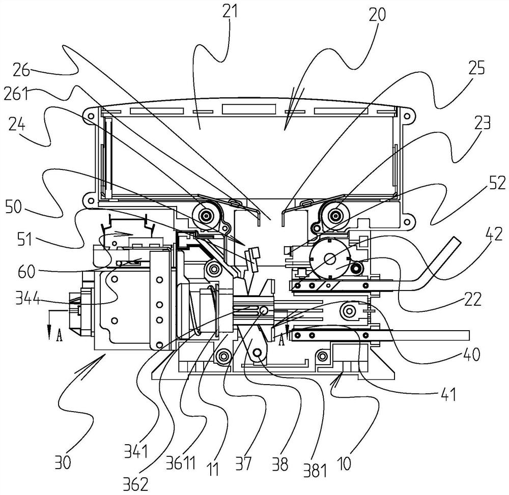
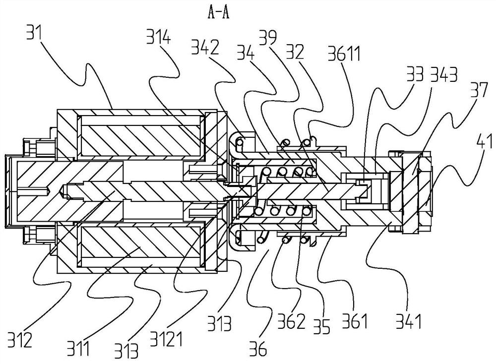
The invention discloses an electromagnetic contactor. The electromagnetic contactor comprises a movable contact, a static contact, a movable auxiliary contact and a static auxiliary contact, wherein the contact attraction assembly comprises an electromagnetic power assembly, a push rod, a swing rod, a movable sleeve and a first compression spring, the end of an iron core of the electromagnetic power assembly makes contact with one end of the push rod, the end, away from the iron core, of the push rod is hinged to the swing rod, one end of the swing rod is hinged to the electromagnetic contactor body, and a movable auxiliary contact is fixedly arranged at the other end; the movable contact is connected to the end, away from the electromagnetic power assembly, of the movable sleeve, the end, away from the movable contact, of the movable sleeve extends towards the iron core and then makes contact with one end of the first compressed spring, and the other end of the first compressed spring makes contact with a supporting part on the iron core; the iron core pushes the push rod to move towards the end where the movable contact is located, pushes the swing rod to rotate around the hinged shaft of the push rod and the electromagnetic contactor body, drives the movable auxiliary contact to move towards the static auxiliary contact and then makes contact with the static auxiliary contact, and meanwhile the iron core extrudes the first compressed spring so that the movable sleeve can drive the movable contact to make contact with the static contact.

Description

technical field [0001] The invention belongs to the technical field of contactors, in particular to an electromagnetic contactor. Background technique [0002] The converter installed in the traction main circuit on electric locomotives and other locomotives equipped with electric transmissions. The function of the traction converter is to convert the electric energy between the DC system and the AC system, and to control and regulate various traction motors, thereby controlling the operation of the locomotive. [0003] In order to realize the separation and closing of the input end of the traction converter and the secondary traction winding of the main transformer, it is necessary to install an electromagnetic contactor in the traction auxiliary converter of the centralized power train; although the existing electromagnetic contactor can realize the auxiliary converter However, due to the high voltage and large current between the input terminal of the converter and the s...

Claims


Application Information

Patent Timeline
Patent Type & Authority Applications(China)
IPC IPC(8): H01H50/54H01H9/30
CPCH01H9/30H01H50/54
Inventor 叶辉浩樊林清
Owner JIAXING SAITIELONG ELECTRIC
Why Eureka
Try Eureka