Household clothes hanger

A technology for clothes and home use, applied in the field of hangers, can solve problems such as difficult to dry, dry, easy to be blown down by the wind, high center of gravity, etc., and achieve the effect of safe drying of clothes

Inactive Publication Date: 2021-04-30
杭州塔姆贸易有限公司
View PDF0 Cites 0 Cited by
  • Summary
  • Abstract
  • Description
  • Claims
  • Application Information

AI Technical Summary

Problems solved by technology

[0004] In rural areas, people usually use bamboo to make support frames and clothes hangers. In the windy season, the wind blows the clothes hangers to slide on the clothes hangers and gathers together, making it difficult to air and dry, and the support frames are relatively light. After hanging clothes on the hanger, the center of gravity is high, and it is easy to be blown down by the wind, causing the clothes to fall on the ground and pollute again

Method used


Image

  • Household clothes hanger
  • Household clothes hanger
  • Household clothes hanger

Examples


Embodiment 1

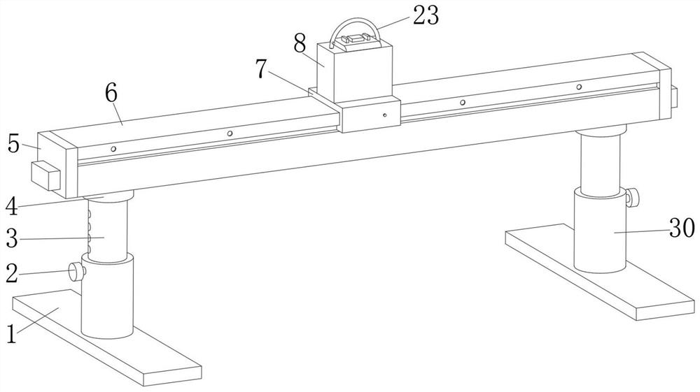
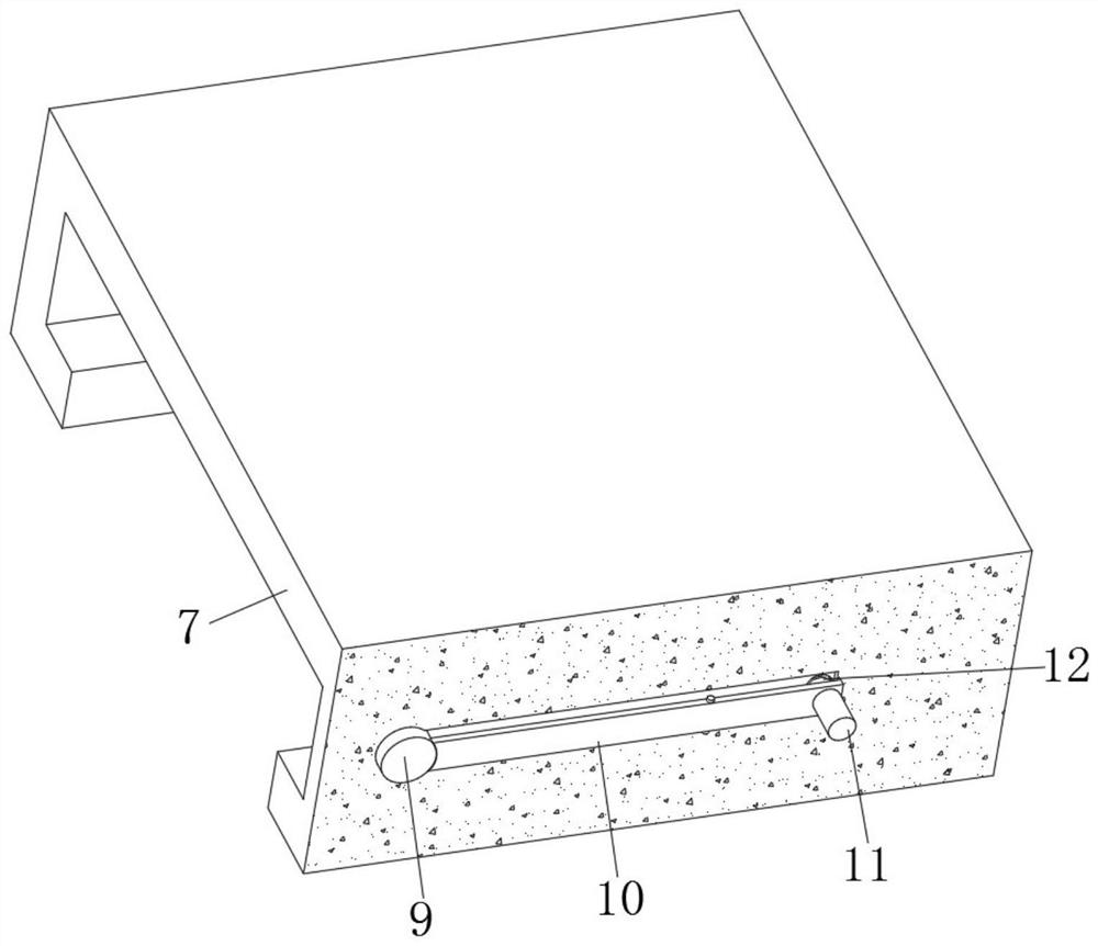
[0032] refer to Figure 1-5 , a household clothes hanger, comprising a support mechanism, a cross bar 6, a fixing mechanism, the outer walls of the left and right sides of the cross bar 6 are provided with chutes, and the inner wall of the chute is slidably connected with a first slider 7, the first slider The inside of 7 is provided with a first groove, and the inner wall of the first groove is rotatably connected with a first movable plate 10, and one end of the first movable plate 10 is fixedly equipped with a first insertion rod 9, and one of the first movable plate 10 One end of the side outer wall away from the first insertion rod 9 is fixed with a first round rod 11 by a screw, the inner wall of the first groove is provided with a first circular groove, and the inner wall of the first circular groove is fixedly equipped with a first spring 12, the first One end of the spring 12 is connected with a side outer wall of the first movable plate 10, and a side outer wall of t...

Embodiment 2

[0043] refer to Figure 6-7 , a household clothes hanger. Compared with Embodiment 1, this embodiment also includes feet 25 that are rotatably connected to the four corners of the base plate 1, and the inside of the base plate 1 is provided with a third circular groove, and one side of the third circular groove The inner wall is fixedly connected with a third spring 26, one end of the third spring 26 is fixedly connected with a third inserting rod 28, the outer wall of the third inserting rod 28 is fixedly connected with a second slider 27, and the outer wall of the bottom plate 1 is provided with a socket. The socket coincides with the third plunger 28 .

[0044] Working principle: through the set foot 25, the third spring 26, the second slider 27, and the third insertion rod 28, after placing the bottom plate 1 on the flat ground, turn the foot 25, and the third insertion rod 28 is inserted into the jack, The base plate 1 is stably supported to prevent strong wind from blow...


PUM


Abstract

The invention belongs to the technical field of hangers, particularly relates to a household clothes hanger, and aims to solve a problem that clothes hung on the clothes hanger are easy to blow over. The household clothes hanger comprises a supporting mechanism, a cross rod and a fixing mechanism, wherein sliding grooves are formed in the outer walls of the left side and the right side of the cross rod, and first sliding blocks are slidably connected to the inner walls of the sliding grooves; and a first groove is formed in the first sliding block, a first movable plate is rotatably connected to the inner wall of the first groove, and a first inserting rod is fixedly mounted at one end of the first movable plate. When the first round rod is pressed down, one end of the first movable plate moves, the other end of the first movable plate reversely moves to pull out the first inserting rod from the through hole, move the first sliding block leftwards and rightwards, loosen the first round rod and the first inserting rod and then insert the first inserting rod into the through hole, the first sliding block is fixed, and the clothes hanger is fixed in the fixing mechanism, namely the position of the clothes hanger can be fixed; and the clothes hanger does not slide to change the position, so the clothes are separated to be aired and dried more quickly.

Description

technical field [0001] The invention relates to the technical field of hangers, in particular to a household clothes hanger. Background technique [0002] A hanger is a shelf used to hang clothes. "Luban Jingjiang Mirror" mentioned that there are two kinds of plain clothes hangers and flower clothes hangers, which are relatively rare outside. The clothes hangers of that time were different from the clothes hangers of today. Most of the modern clothes hangers are hooked or branched, and the clothes are mostly hung on the hooks by the neck. The ancient clothes hangers, including the clothes hangers of the Qing Dynasty, were mostly in the form of horizontal bars, with columns on both sides, the base of the upper and lower wooden piers, and a horizontal plate or a cross between the two. A beam was installed on the top of the column. There are dragon and phoenix patterns or Ganoderma lucidum or cloud heads. The Anzhong brand under the horizontal bar is decorated with openwork...

Claims


Application Information

Patent Timeline
Patent Type & Authority Applications(China)
IPC IPC(8): A47G25/06
CPCA47G25/0671
Inventor 朱衷梨周志兵
Owner 杭州塔姆贸易有限公司
Why Eureka
Try Eureka