

PET-CT examining bed
A PET-CT, examination bed technology, used in medical science, patient positioning for diagnosis, instruments for radiological diagnosis, etc. It can improve the efficiency and quality of inspection, avoid conflicts between doctors and patients, and avoid radiation damage.
- Summary
- Abstract
- Description
- Claims
- Application Information
AI Technical Summary
Problems solved by technology
Method used
Image

Examples
Embodiment Construction
[0028] The following clearly and completely describes the technical solutions in the embodiments of the present invention. Obviously, the described embodiments are only some of the embodiments of the present invention, but not all of them. Based on the embodiments of the present invention, all other embodiments obtained by persons of ordinary skill in the art without making creative efforts belong to the protection scope of the present invention.
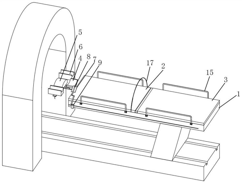
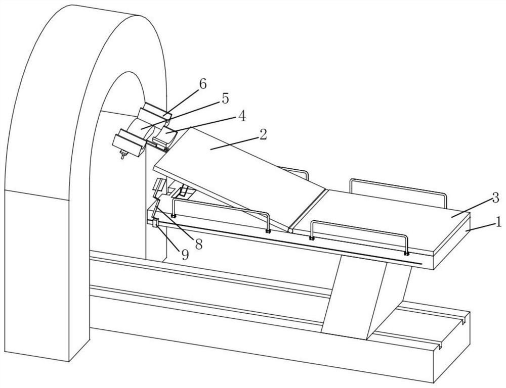
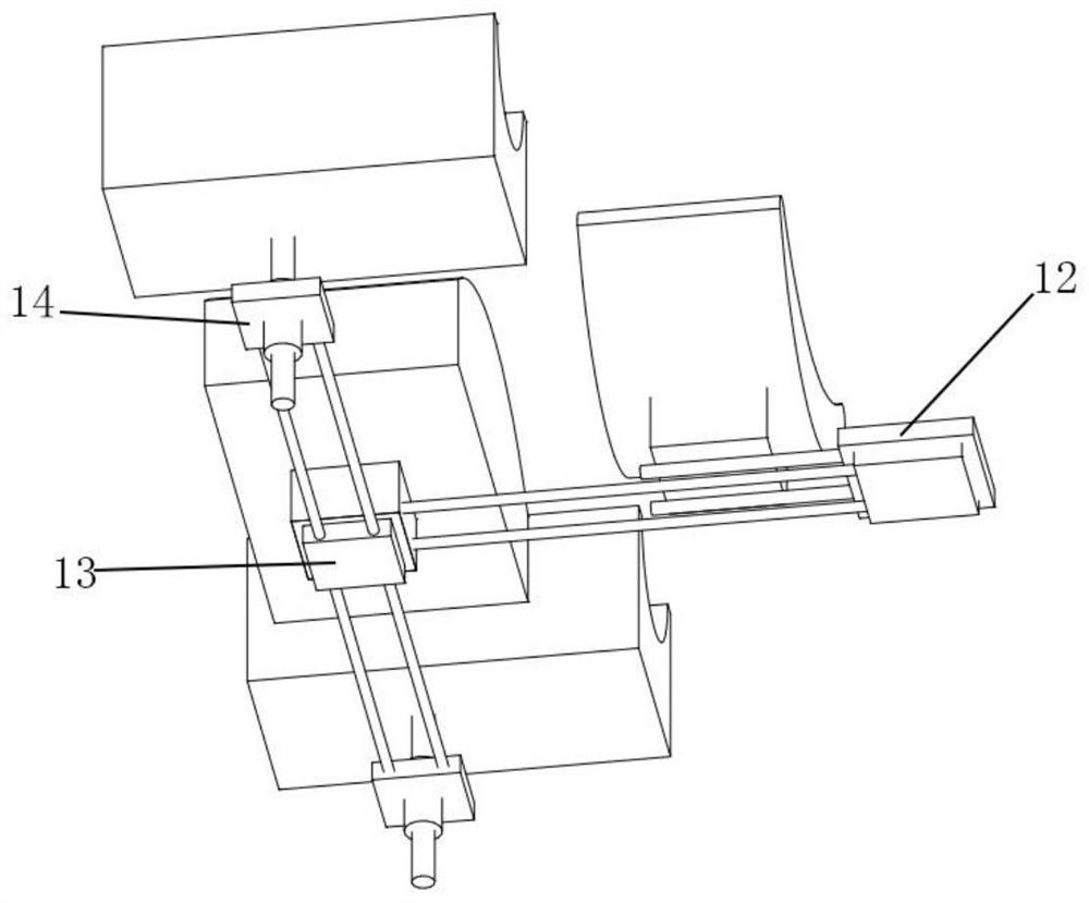
[0029] see Figure 1 to Figure 5 , the present invention provides a PET-CT examination bed, including a bed frame 1, a bed board I2, a bed board II3, a neck support 4, a head support 5 and an upper arm support seat 6, and the bed board I2 and the bed board II3 are installed on the bed frame 1 , the bed board I2 is hinged with the bed board II3, and the bed boards are provided with pads, which can improve the comfort. The bed board I2 and the bed frame 1 are connected with a push device, which can push the bed board I2 up or lay it f...
PUM
 Abstract
Description
Claims
Application Information