
Treatment device and method for efficient solid waste treatment

A processing device and high-efficiency technology, used in grain processing, chemical instruments and methods, solid separation, etc., can solve problems such as insufficient sieve plate cleaning, sieve removal, economic loss, etc. Disperse evenly and improve the effect of screening

Inactive Publication Date: 2021-04-30
辽宁银盛水泥集团有限公司
View PDF6 Cites 8 Cited by
  • Summary
  • Abstract
  • Description
  • Claims
  • Application Information

AI Technical Summary

Problems solved by technology

[0002] With the development of society, cement is used more and more widely. For a long time, it has been widely used as an important cementing material in civil engineering, water conservancy, national defense and other projects. In the process of cement application, there will inevitably be a need for cement Solid waste, if these wastes cannot be processed and utilized, great economic losses will be caused. Therefore, the present invention designs a treatment device and method for high-efficiency solid waste treatment, mainly for the treatment of solid cement waste
[0003] However, in the current solid cement waste treatment device, after the solid waste is crushed, the screening and processing part is not ideal, and it is easy to cause various impurities to remain in the crushed waste recycling, thereby affecting the recovery quality. The waste screening is not uniform enough, it is easy to cause some useful waste to be screened out together with sundries, which will also cause waste. At the same time, the cleaning of the sieve plate during screening is not good enough, resulting in low efficiency of waste treatment

Method used


Image

  • Treatment device and method for efficient solid waste treatment
  • Treatment device and method for efficient solid waste treatment
  • Treatment device and method for efficient solid waste treatment

Examples


Embodiment Construction

[0028] The technical solutions in the embodiments of the present invention will be clearly and completely described below in conjunction with the embodiments of the present invention. Apparently, the described embodiments are only some, not all, embodiments of the present invention. Based on the embodiments of the present invention, all other embodiments obtained by persons of ordinary skill in the art without making creative efforts belong to the protection scope of the present invention.

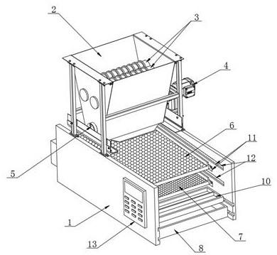
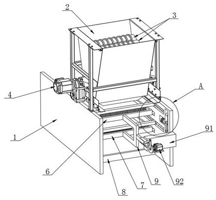
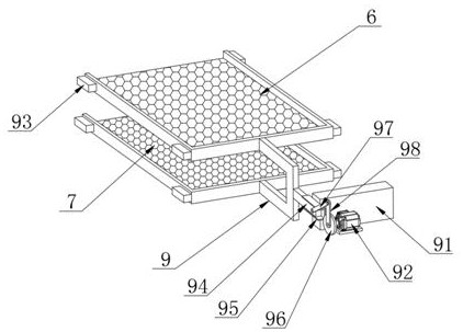
[0029] see Figure 1~6 , in an embodiment of the present invention, a treatment device for high-efficiency solid waste treatment, including two vertical boards 1 correspondingly arranged, a crushing mechanism is installed above one end of the two vertical boards 1, and the two vertical boards 1 are arranged side by side up and down An upper sieve plate 6 and a lower sieve plate 7 are provided, a receiving hopper 8 is provided at the bottom between the two vertical plates 1, and a The slag...


PUM


Abstract

The invention relates to the technical field of cement waste, and discloses an efficient solid waste treatment device. The efficient solid waste treatment device comprises two vertical plates arranged correspondingly, wherein a crushing mechanism is mounted above one ends of the two vertical plates, an upper sieve plate and a lower sieve plate are arranged between the two vertical plates up and down in parallel, a receiving hopper is arranged at the bottom between the two vertical plates, and a slag receiving hopper is arranged between the two vertical plates and located under one end of the upper sieve plate and one end of the lower sieve plate, the middles of the rear surfaces of the upper sieve plate and the lower sieve plate are jointly connected with a reciprocating motion mechanism, and sweeping mechanisms are arranged in the positions, corresponding to the upper sieve plate and the lower sieve plate, of the inner sides of the vertical plates. When the crushed waste is screened, the waste can fall onto the screen plate to be more rapidly and uniformly dispersed, so that the screening efficiency of the screen plate on the waste is improved; and moreover, the screened impurities and metal substances can be classified, so that the solid waste treatment efficiency is further improved.

Description

technical field [0001] The invention relates to the technical field of cement waste treatment, in particular to a treatment device and method for high-efficiency solid waste treatment. Background technique [0002] With the development of society, cement is used more and more widely. For a long time, it has been widely used as an important cementing material in civil engineering, water conservancy, national defense and other projects. In the process of cement application, there will inevitably be a need for cement Solid waste, if these wastes cannot be processed and utilized, will cause great economic losses. Therefore, the present invention designs a treatment device and method for high-efficiency solid waste treatment, mainly for the treatment of solid cement waste. [0003] However, in the current solid cement waste treatment device, after the solid waste is crushed, the screening and processing part is not ideal, and it is easy to cause various impurities to remain in th...

Claims


Application Information

Patent Timeline
Patent Type & Authority Applications(China)
IPC IPC(8): B02C4/08B02C4/30B02C4/28B02C23/14B02C23/16B02C23/08B07B1/28B07B1/42B07B1/46B07B1/52B03C1/02
CPCB02C4/08B02C4/28B02C4/30B02C23/08B02C23/14B02C23/16B02C2023/165B02C2201/06B03C1/02B07B1/28B07B1/42B07B1/4663B07B1/522B07B2201/04
Inventor 吴昊霖
Owner 辽宁银盛水泥集团有限公司
Learn More