Eureka AIR delivers breakthrough ideas for toughest innovation challenges, trusted by R&D personnel around the world.

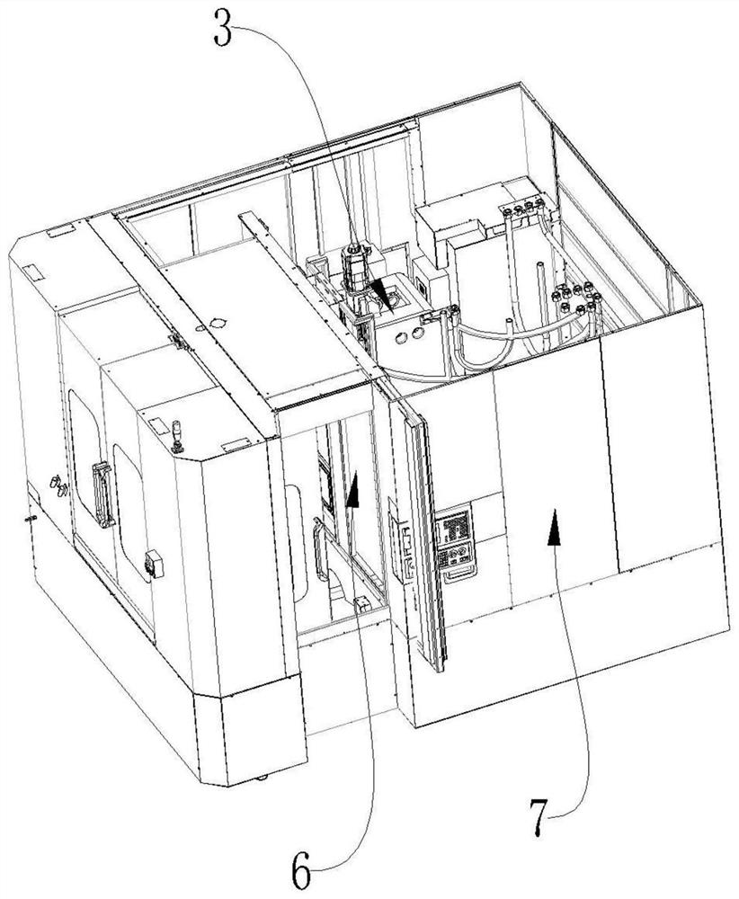
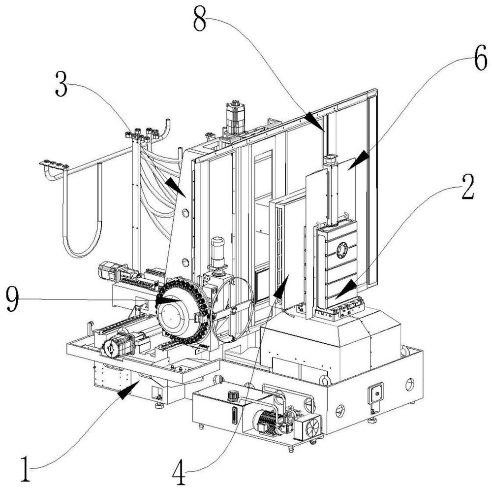
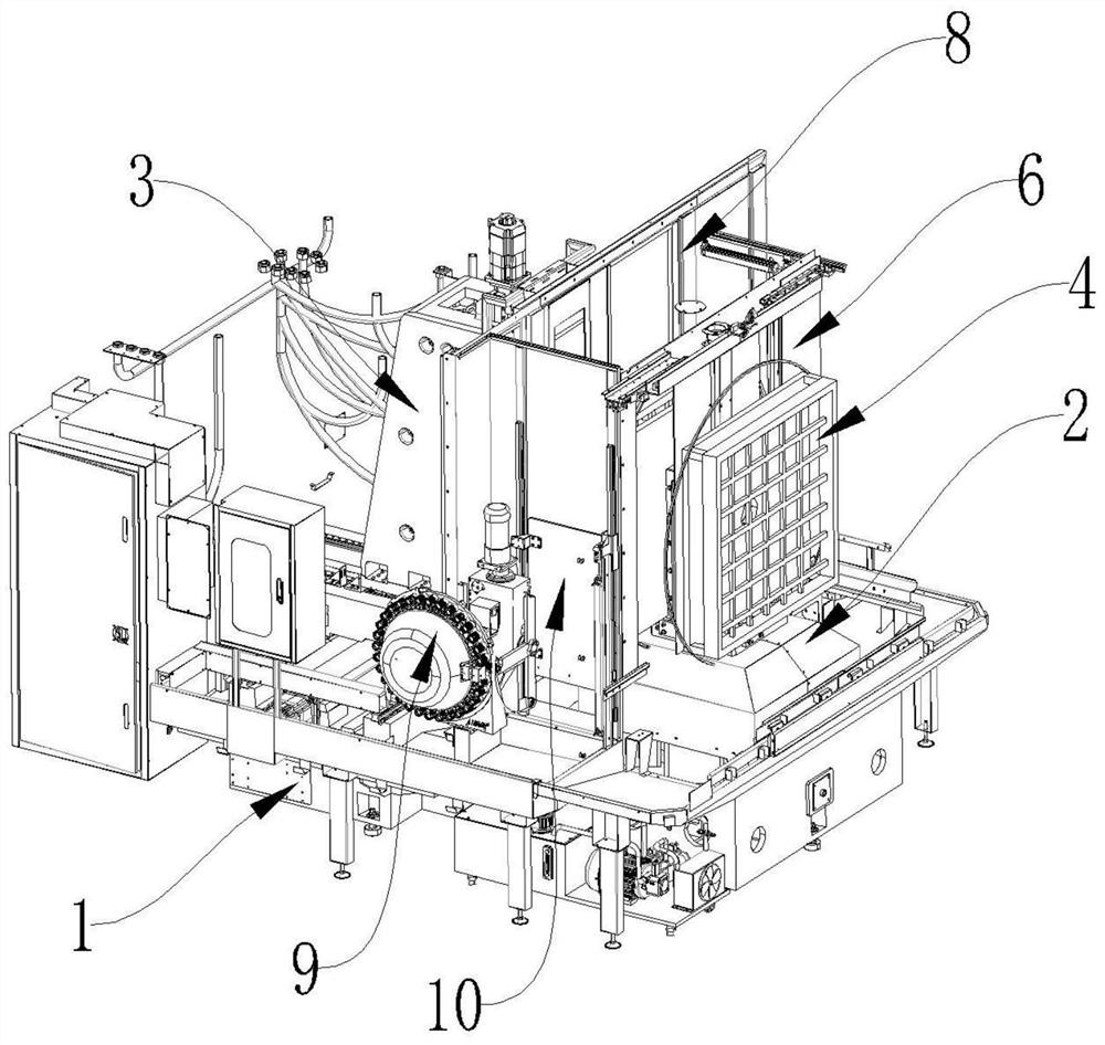
Numerical control machining center capable of achieving multi-face machining through one-time clamping

A multi-faceted machining and machining center technology, applied in metal processing equipment, metal processing mechanical parts, clamping and other directions, can solve problems such as affecting production efficiency and reducing machining accuracy

Pending Publication Date: 2021-04-30
FOSHAN PRATIC CNC SCI & TECH
View PDF0 Cites 2 Cited by
  • Summary
  • Abstract
  • Description
  • Claims
  • Application Information

AI Technical Summary

Problems solved by technology

[0004] The purpose of the present invention is to propose a numerical control machining center capable of multi-face machining in one clamping, aiming to solve the technical problems in the prior art that multiple clamping is required for workpieces requiring multi-face machining, thereby affecting production efficiency and reducing machining accuracy

Method used


Image

  • Numerical control machining center capable of achieving multi-face machining through one-time clamping
  • Numerical control machining center capable of achieving multi-face machining through one-time clamping
  • Numerical control machining center capable of achieving multi-face machining through one-time clamping

Examples


Embodiment Construction

[0031] The following will clearly and completely describe the technical solutions in the embodiments of the present invention with reference to the accompanying drawings in the embodiments of the present invention. Obviously, the described embodiments are only part of the embodiments of the present invention, not all of them. Based on the embodiments of the present invention, all other embodiments obtained by persons of ordinary skill in the art without creative efforts fall within the protection scope of the present invention.

[0032] It should be noted that if there is a directional indication (such as up, down, left, right, front, back...) in the embodiment of the present invention, the directional indication is only used to explain the position in a certain posture (as shown in the accompanying drawing). If the specific posture changes, the directional indication will also change accordingly.

[0033] In addition, if there are descriptions involving "first", "second" and ...


PUM


Abstract

The invention relates to the technical field of numerical control machining equipment, in particular to a numerical control machining center capable of achieving multi-face machining through one-time clamping. The numerical control machining center comprises a lathe bed, a multi-station clamp mechanism and a machining mechanism. The multi-station clamp mechanism comprises a B-axis rotary table, a rotary table stand column, a C-axis rotary table and a first clamp fixing base, the B-axis rotary table is installed on the lathe bed, the rotary table stand column is rotatably installed on the B-axis rotary table, the C-axis rotary table is installed on the rotary table stand column, and the first clamp fixing base is rotatably installed on the C-axis rotary table; a rotating shaft of the first clamp fixing base is perpendicular to a rotating shaft of the rotary table stand column; and the machining mechanism is installed on the lathe bed, the machining mechanism comprises a machine tool spindle, and the machine tool spindle corresponds to a clamp installed on the first clamp fixing base. Through rotation of the rotary table stand column and the first clamp fixing base, five faces of a workpiece can be machined by the machine tool spindle under the condition of one-time clamping, and therefore the machining production efficiency is greatly improved, and meanwhile the situation that the machining precision is lower due to multiple times of clamping is avoided.

Description

technical field [0001] The invention relates to the technical field of numerical control machining equipment, in particular to a numerical control machining center capable of multi-face machining in one clamping. Background technique [0002] With the continuous development of science and technology, various machining centers have emerged to adapt to different processing situations and processing requirements, including vertical machining centers, horizontal machining centers and vertical-horizontal composite machining centers. Due to structural problems, aluminum scraps are easy to block blind holes or enter other holes during processing, causing poor quality problems, so they are rarely used; vertical and horizontal composite machining centers can achieve horizontal and vertical spindles. The purpose of processing different workpieces in different directions at the same time, so as to improve the processing efficiency of workpieces, but at the same time, due to its particu...

Claims


Application Information

Patent Timeline
IPC IPC(8): B23Q3/12B23Q11/08
CPCB23Q3/12B23Q11/08
Inventor 李哲彭刚李爱军沈成辉赵小雨
Owner FOSHAN PRATIC CNC SCI & TECH
Why Eureka
Eureka Blog
Learn More