Knife grinder capable of being adjusted at multiple angles

A knife sharpening machine, multi-angle technology, applied in the direction of grinding frame, grinding slide, grinding bed, etc., can solve the problems of increasing production cost, occupying workshop space, increasing tool cost, etc.

Inactive Publication Date: 2021-04-30
JIANGSU TENGFEI CNC MACHINERY CO LTD
View PDF9 Cites 2 Cited by
  • Summary
  • Abstract
  • Description
  • Claims
  • Application Information

AI Technical Summary

Problems solved by technology

At present, in order to meet the various requirements of different knives, a variety of different types of sharpening machines are generally developed to meet the relevant needs, which obviously increases the cost of knife production. For enterprises that produce various knives, it is necessary to purchase multiple equipment. It not only takes up the space of the factory building, but also requires more operators to operate, which greatly increases the related production costs

Method used


Image

  • Knife grinder capable of being adjusted at multiple angles
  • Knife grinder capable of being adjusted at multiple angles
  • Knife grinder capable of being adjusted at multiple angles

Examples


Embodiment 1

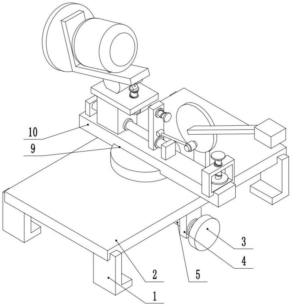
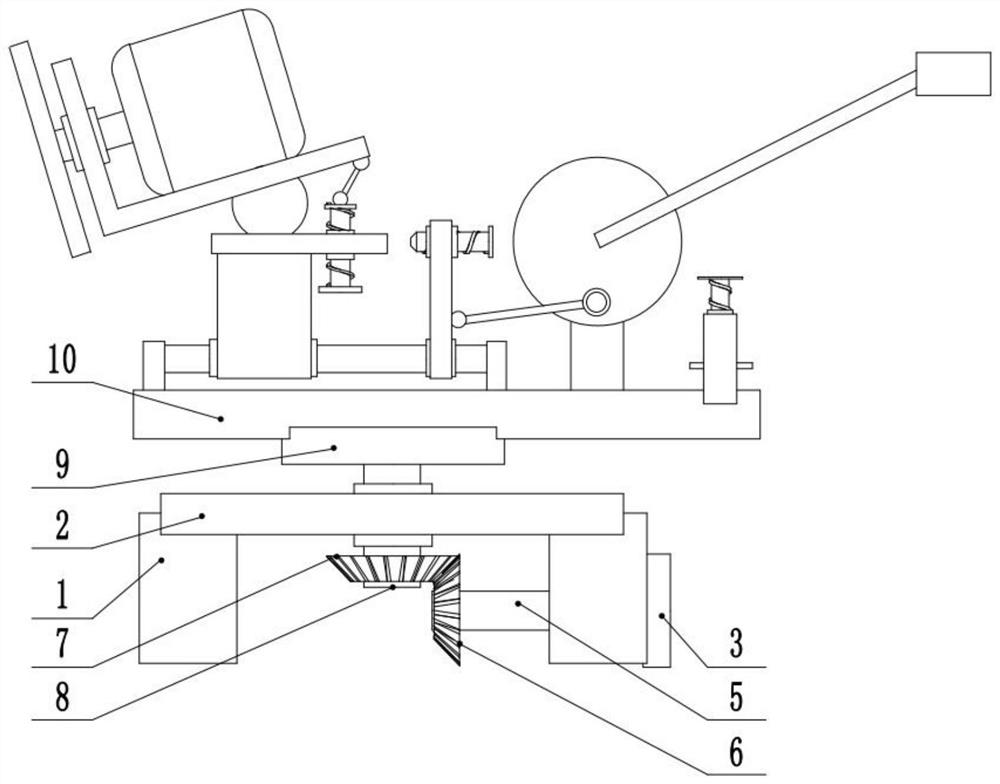
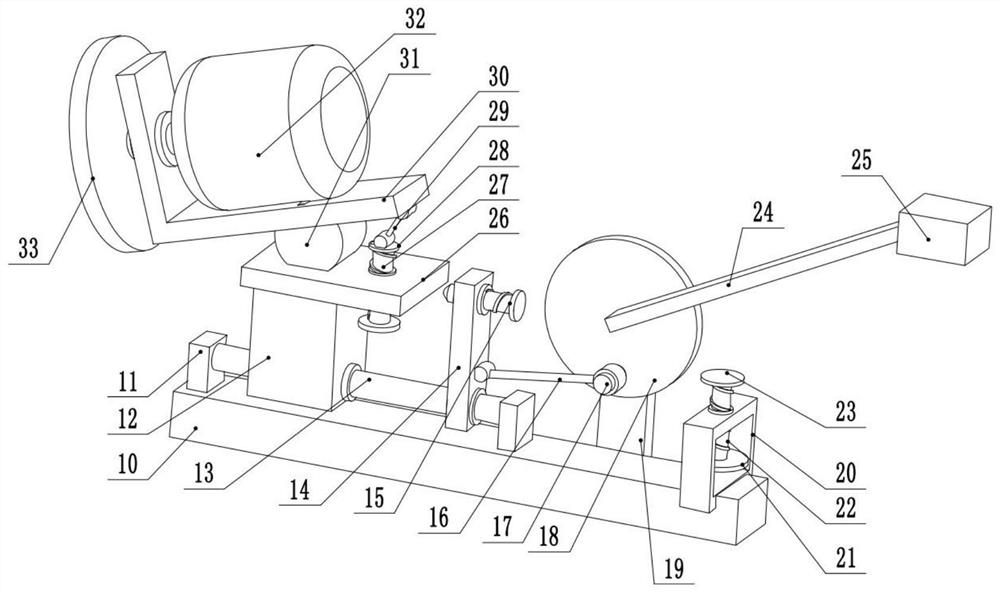
[0026] see Figure 1-4 , a multi-angle adjustable knife grinder, comprising a fixed table 2, the middle part of the fixed table 2 is rotatably connected to the middle part of the second rotating shaft 8, the upper end of the second rotating shaft 8 is provided with a first rotating disk 9, and the first rotating disk 9 The middle part is fixedly connected to the middle part of the rotating plate 10. The middle part of the lower surface of the fixed table 2 is provided with a first rotating shaft 5, and the left end of the first rotating shaft 5 is provided with a first bevel gear 6, the first bevel gear 6 meshes with the second bevel gear 7, and the second bevel gear 7 is fixedly connected The lower end of the second rotating shaft 8. The right side of the lower surface of the fixed table 2 is provided with a first fixed plate 4 , the middle part of the first fixed plate 4 is rotatably connected to the middle part of the first rotating shaft 5 , and the right end of the first...

Embodiment 2

[0030] see figure 1 , the other content of this embodiment is the same as that of Embodiment 1, the difference is that: the lower surface of the fixed platform 2 is provided with mounting seats 1 on the front and rear sides. This device can be used in conjunction with some tool fixing devices, or directly placed in some processing equipment. It is not necessary to remove the tool during the process of grinding the tool of the processing equipment, which is convenient for operation. It is convenient for the installation of the whole device.

[0031] In the implementation process of the present invention, the device is fixed in the tool clamping device. At this time, the first runner 3 is rotated, and the first runner 3 drives the first rotating shaft 5 to rotate. The first rotating shaft 5 passes through the first bevel gear 6 and The second bevel gear 7 drives the second rotating shaft 8 to rotate, the second rotating shaft 8 drives the first rotating disk 9 to rotate, and th...


PUM


Abstract

The invention relates to the technical field of knife grinders, and discloses a knife grinder capable of being adjusted at multiple angles. The knife grinder comprises a fixed table, wherein the middle of the fixed table is rotationally connected with the middle of a second rotating shaft, a first rotating disc is arranged at the upper end of the second rotating shaft, the middle of the first rotating disc is fixedly connected with the middle of a rotating plate, a second fixing plate is arranged on the left side of the upper surface of the rotating plate, a guide rod is arranged in the middle of the second fixing plate, a sliding base is slidably connected to the middle of the guide rod, a fourth fixing plate is arranged on the upper portion of the sliding base, a rotating base is arranged on the left side of the upper surface of the fourth fixing plate, a mounting support is arranged at the upper portion of the rotating base, a driving motor is arranged on the upper portion of the mounting support, and an output shaft of the driving motor is fixedly connected with a grinding head. According to the knife grinder capable of being adjusted at multiple angles, the front-back angle and the pitching angle of the grinding head can be adjusted by arranging the first rotating disc and the rotating base, and therefore the knife grinder can meet the grinding treatment work of various knives.

Description

technical field [0001] The invention relates to the technical field of knife sharpeners, in particular to a multi-angle adjustable knife sharpener. Background technique [0002] Knife sharpeners are used to sharpen various knives such as kitchen knives and scissors. Because different knives have different requirements for the blade surface, for example, some require a flat surface, while others have a curved surface requirement, and the requirements for the shape of the blade are not the same, which requires different sharpening angles to meet the corresponding requirements. At present, in order to meet the various requirements of different knives, a variety of different types of sharpening machines are generally developed to meet the relevant needs, which obviously increases the cost of knife production. For enterprises that produce various knives, it is necessary to purchase multiple equipment. It not only occupies the workshop space, but also requires more operators to o...

Claims


Application Information

Patent Timeline
Patent Type & Authority Applications(China)
IPC IPC(8): B24B3/52B24B3/54B24B47/22B24B41/02B24B47/04
CPCB24B3/52B24B3/54B24B47/22B24B41/02B24B47/04
Inventor 陈吟明储进
Owner JIANGSU TENGFEI CNC MACHINERY CO LTD
Why Eureka
Try Eureka