
Drilling equipment with dustproof function for municipal building

A technology for drilling equipment and construction, which is applied in the field of drilling equipment for municipal buildings, and can solve problems such as being difficult to clean, falling on the wall, and bodily injury.

Pending Publication Date: 2021-04-30
廖冬花
View PDF0 Cites 2 Cited by
  • Summary
  • Abstract
  • Description
  • Claims
  • Application Information

AI Technical Summary

Problems solved by technology

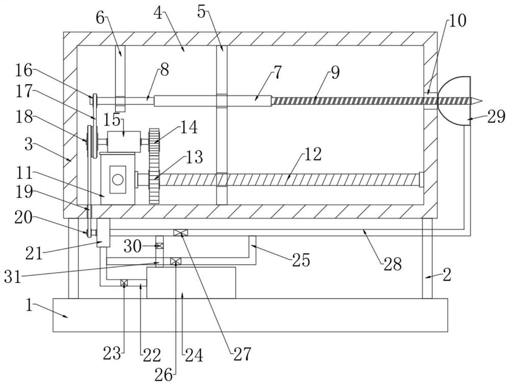
[0003] At present, when drilling holes in buildings, most of them are manual hand-held electric drills. If there are many holes to drill, manual hand-held electric drills will be exhausting, and there will be dust during the drilling process, which will not only fall on the wall , is not easy to clean, and is inhaled by the staff, which will cause damage to the body. Therefore, we have designed a municipal building drilling equipment with dust-proof function to solve the above problems

Method used


Image

  • Drilling equipment with dustproof function for municipal building
  • Drilling equipment with dustproof function for municipal building
  • Drilling equipment with dustproof function for municipal building

Examples


Embodiment 1

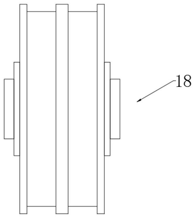
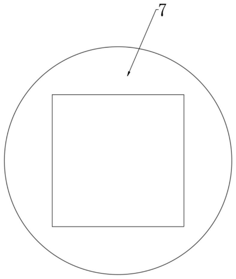
[0028] refer to Figure 1-3 , a kind of drilling equipment for municipal buildings with dustproof function, comprising a base 1, the base 1 can be installed on the lifting frame, so that the height of the drill bit 9 can be adjusted, and the drilling operation can be performed on positions of different heights; the base 1 Four support columns 2 are fixedly connected, and the upper ends of the four support columns 2 are fixedly connected with a box body 3, and the box body 3 is provided with an installation cavity 4, and the inner bottom of the installation cavity 4 is fixedly connected with a servo motor 11, and the servo motor 11 The output end of the screw rod 12 is fixedly connected with it, and the other end of the screw rod 12 is connected with the inner wall of the installation cavity 4 in rotation.

[0029] There is a riser 5 slidingly connected in the installation cavity 4, that is, from figure 1 It can be seen that the vertical board 5 can slide left and right. In ac...

Embodiment 2

[0040] refer to Figure 4-6 The difference between this embodiment and Embodiment 1 is that in this embodiment, the end of the suction cover 39 opposite to the box body 3 is provided with an annular groove 39, and an annular airbag 40 is installed in the annular groove 39, and the inner wall of the installation cavity 4 is fixed. Connected with a piston cylinder 36, the piston cylinder 36 is slidingly connected with a piston 37, the piston cylinder 36 communicates with the annular air bag 40 through the gas delivery pipe 38, and the opposite end of the piston 37 and the gas delivery pipe 38 is fixedly connected with a piston rod 35, and the piston rod 35 The other end of the second hollow rod 33 is fixedly connected with the second hollow rod 33, and the driving rod 32 is slidably connected with the vertical plate 5. The driving rod 32 and the second hollow rod 33 are fixedly connected with a spring 34.

[0041] In this embodiment, when the vertical plate 5 moves, the vertica...


PUM


Abstract

The invention discloses drilling equipment with a dustproof function for a municipal building. The drilling equipment comprises a base, four supporting columns are fixedly connected to the base, the upper ends of the four supporting columns are jointly and fixedly connected with a box body, a mounting cavity is formed in the box body, a servo motor is fixedly connected to the inner bottom of the mounting cavity, a screw rod is fixedly connected to the output end of the servo motor, the other end of the screw rod is rotationally connected with the inner wall of the mounting cavity, a vertical plate is slidably connected into the mounting cavity, the screw rod penetrates through the vertical plate and is in threaded connection with the vertical plate, a first hollow rod rotationally connected with the vertical plate is arranged on the vertical plate in a penetrating mode, and one end of the first hollow rod is fixedly connected with a drill bit. The drilling equipment is reasonable in structure, drilling operation on the municipal building can be achieved through one servo motor, dust generated in the drilling process can be removed, the wall surface can be protected, and safety guarantee is provided for the body of a worker.

Description

technical field [0001] The invention relates to the technical field of municipal buildings, in particular to a drilling device for municipal buildings with a dust-proof function. Background technique [0002] Municipal buildings refer to public buildings funded by the government, and generally refer to various administrative buildings and buildings serving the public in the planning area, including government buildings, public entertainment facilities, urban transportation facilities, educational, scientific and cultural institution buildings, medical and health institutions Construction, etc.; construction exists in all aspects of people's lives, and it is also an industry that needs continuous development and innovation in the future. [0003] At present, when drilling holes in buildings, most of them are manual hand-held electric drills. If there are many holes to drill, manual hand-held electric drills will be exhausting, and there will be dust during the drilling proces...

Claims


Application Information

Patent Timeline
Patent Type & Authority Applications(China)
IPC IPC(8): B28D1/14B28D7/00
CPCB28D1/146B28D7/00
Inventor 廖冬花
Owner 廖冬花
Learn More