Handheld cutting machine and grooving machine

A cutting machine and slotting machine technology, applied in stone processing tools, working accessories, manufacturing tools, etc., can solve the problems of affecting heat dissipation effect, unreasonable fan design, short service life, etc., and achieve reasonable air inlet and outlet, Improve the effect of ventilation and heat dissipation, and improve the service life

Pending Publication Date: 2021-04-30
ZHEJIANG BODA IND
View PDF0 Cites 3 Cited by
  • Summary
  • Abstract
  • Description
  • Claims
  • Application Information

AI Technical Summary

Problems solved by technology

But there are following deficiencies in the use process: one, because the motor rear bearing is directly arranged on the rear side wall of the casing, the casing is made of engineering plastics, the mechanical strength is low, the heat dissipation effect is not ideal, and the working stability of the motor is poor. short service life
Second, the design of the fan is unreasonable, the air exhaust is not smooth, the resistance is large, and it is easy to generate eddy current and noise, which directly affects the heat dissipation effect and causes the motor to heat up and not work normally.
The third is that the dust-proof performance of the rear bearing of the motor is poor. During use, dust and foreign matter can easily enter the casing, resulting in a decrease in the lubrication effect of the bearing or foreign matter directly entering the bearing, causing the bearing to rotate inflexibly or even get stuck, and cannot work normally.
Fourth, the dustproof and waterproof effect of the switch is poor
Fifth, there is a lot of dust in cutting and grooving, the working environment is poor, and the dust removal effect is not ideal
In response to the above problems, many manufacturers and people of insight have developed and developed, but so far no ideal products have come out.

Method used


Image

  • Handheld cutting machine and grooving machine
  • Handheld cutting machine and grooving machine
  • Handheld cutting machine and grooving machine

Examples


Embodiment Construction

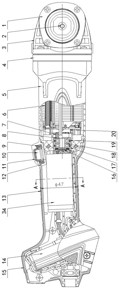
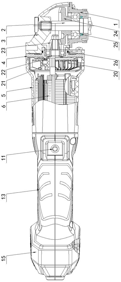
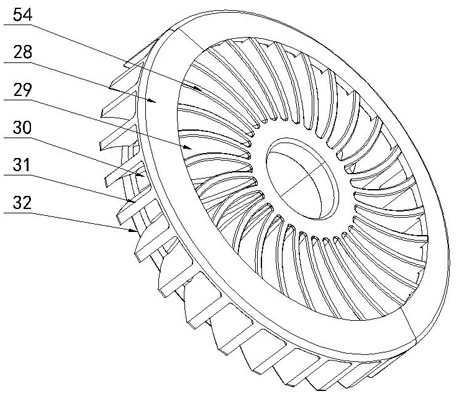
[0028] Figure 1 to Figure 7As shown, the present invention creates a specific embodiment of a hand-held cutting machine and slotting machine, which includes a main machine and a cutting device, and the main machine includes a rear handle 13, a casing 5, a brushless motor 6, an intermediate cover 4, and a transmission mechanism , the motor shaft 20 is fixed with a fan 21, the rear side wall of the casing 5 is provided with a metal bushing 17 connected by injection molding, and the metal bushing 17 is provided with a double bearing 18 through a first sealing ring 19 structure, the front end of the motor shaft 20 is rotatably set on the middle cover 4 through a single bearing structure, the rear end of the motor shaft 20 is rotatably set on the metal bush 17 through a double bearing 18 structure, and the rear end of the metal bush 17 The rubber dustproof cover 16 that is provided with seal fit is fixed on the motor shaft 20 with the dustproof and waterproof plastic ring 7 positi...


PUM

PropertyMeasurementUnit
heightaaaaaaaaaa

Abstract

The invention discloses a handheld cutting machine and grooving machine. The handheld cutting machine and grooving machine comprises a main machine and a cutting device, wherein the main machine comprises a rear handle, a machine shell, a brushless motor, a middle cover and a transmission mechanism, a fan is fixed to a motor shaft, a metal bush connected into a whole through injection molding is arranged on the rear side wall of the machine shell, a double-bearing structure is arranged in the metal bush through a first sealing ring, the front end of the motor shaft is arranged on the middle cover through a single-bearing structure, the rear end of the motor shaft is arranged on the metal bush through a double-bearing structure, a rubber dustproof cover in sealing fit is arranged at the rear end of the metal bush, a plastic impeller located on the front side of the metal bush is fixed to the motor shaft, and centrifugal blades are uniformly distributed on the plastic impeller. After the structure is adopted, the handheld cutting machine and grooving machine has the advantages of simple and reasonable structure, convenience in operation and use, stability in work, good ventilation and heat dissipation effects, dust prevention, water prevention, reliability, long service life and the like.

Description

technical field [0001] The invention relates to the technical field of electric cutting tools, in particular to a hand-held cutting machine and slotting machine used for cutting floors, walls and stones. Background technique [0002] Cutting machine and slotting machine is a kind of cutting and slotting machine mainly used for floor and wall surface. Due to its fast cutting speed and high work efficiency, it is very popular among users. But there are following deficiencies in the use process: one, because the motor rear bearing is directly arranged on the rear side wall of the casing, the casing is made of engineering plastics, the mechanical strength is low, the heat dissipation effect is not ideal, and the working stability of the motor is poor. Short service life. The second is that the design of the fan is unreasonable, the air exhaust is not smooth, the resistance is large, and it is easy to generate eddy currents and noises, which directly affects the heat dissipation...

Claims


Application Information

Patent Timeline
Patent Type & Authority Applications(China)
IPC IPC(8): B28D1/22B28D1/24B28D7/00B28D7/02
CPCB28D1/228B28D1/24B28D7/00B28D7/02
Inventor 胡丽姬吴浩东胡新昌
Owner ZHEJIANG BODA IND
Why Eureka
Try Eureka