
Pressing plate jig for thin film bonding, pressing structure and thin film bonding device

A technology for fixing structures and pressing plates, which can be applied to household appliances, other household appliances, flat products, etc., and can solve problems affecting the 90° movement of the pressure head

Active Publication Date: 2021-04-30
INTERFACE TECH CHENGDU CO LTD +3
View PDF9 Cites 0 Cited by
  • Summary
  • Abstract
  • Description
  • Claims
  • Application Information

AI Technical Summary

Problems solved by technology

But found in the application, such as Figure 7 As shown, on the one hand, the heat-resistant adhesive tape 800 will still undergo certain deformation at high temperature; 801 affects the movement of the indenter 900, so the method of sticking tape is not suitable for products of various sizes, and it will also cause new bad problems

Method used


Image

  • Pressing plate jig for thin film bonding, pressing structure and thin film bonding device
  • Pressing plate jig for thin film bonding, pressing structure and thin film bonding device
  • Pressing plate jig for thin film bonding, pressing structure and thin film bonding device

Examples


Embodiment 1

[0064] Embodiment 1: the tank body 110, the first auxiliary tank 140 and the second auxiliary tank 150 are all rectangular, the first auxiliary tank 140 and the second auxiliary tank 150 are arranged symmetrically with respect to the tank body 110, and the first distance L1 is 300 μm. The width of the first auxiliary groove 140 and the second auxiliary groove 150 , that is, the second distance L2 is 250 μm, and the distance between the first auxiliary groove 140 , the second auxiliary groove 150 and the tank body 110 , that is, the third distance L3 is 250 μm. The stress distribution simulation analysis results are as follows: Figure 16 As shown, the corresponding press gap analysis is as follows Figure 17 As shown, the maximum gap value L0 of the gap caused by pressing is 0.0019169 mm, which is about 1.92 μm.

Embodiment 2

[0065] Example 2: Different from Example 1, the third spacing L3 is 500 μm, and the stress distribution simulation analysis results are as follows Figure 18 As shown, the corresponding press gap analysis is as follows Figure 19 As shown, the maximum gap value L0 of the gap caused by pressing is about 2.91 μm.

Embodiment 3

[0066] Example 3: Different from Example 1, the third spacing L3 is 750 μm, and the stress distribution simulation analysis results are as follows Figure 20 As shown, the corresponding press gap analysis is as follows Figure 21 As shown, the maximum gap value L0 of the gap caused by pressing is about 4.95 μm.


PUM

PropertyMeasurementUnit
Widthaaaaaaaaaa

Abstract

The invention relates to a pressing plate jig for thin film bonding, a pressing structure and a thin film bonding device. The pressing plate jig comprises a body and pressing positions extending to the two sides of the body, a groove body is formed in a pressing area in the middle of the body, the pressing plate jig is further provided with two auxiliary grooves in the body, and the groove body is located between the two auxiliary grooves. Stress is released in the form of forming the auxiliary grooves, and tests prove that a gap between the pressing plate jig and a thin film can be effectively reduced when the thin film is bonded, so that on one hand, the probability of position deviation of the thin film is reduced; on the other hand, even if deviation occurs, the offset can be greatly reduced due to the fact that the maximum gap value of the gap is reduced, and therefore poor film bonding can be avoided; and on the other hand, the existing pressing plate jig is further treated, the existing pressing plate jig and manufacturing equipment thereof can be directly utilized, a mold or a supply chain of the existing pressing plate jig does not need to be replaced, the newly-added cost is extremely low, the difficulty of technical innovation is reduced, and application and popularization are facilitated.

Description

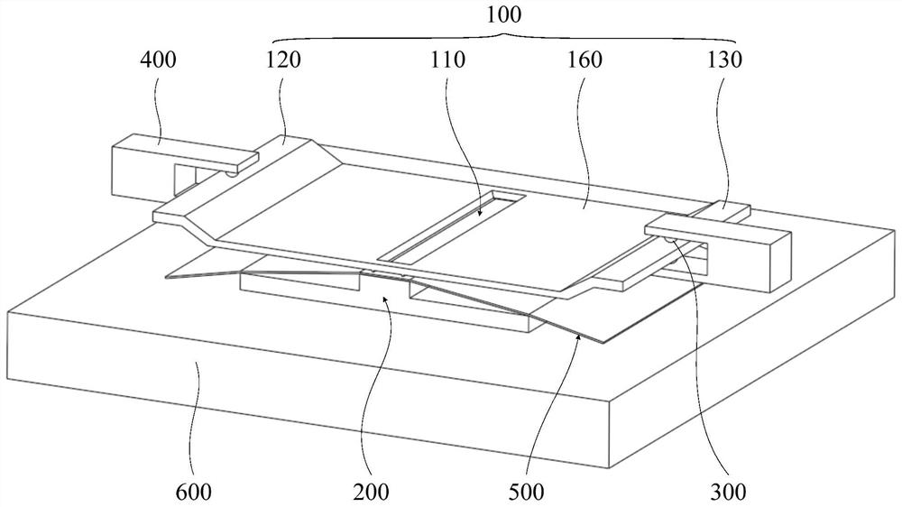
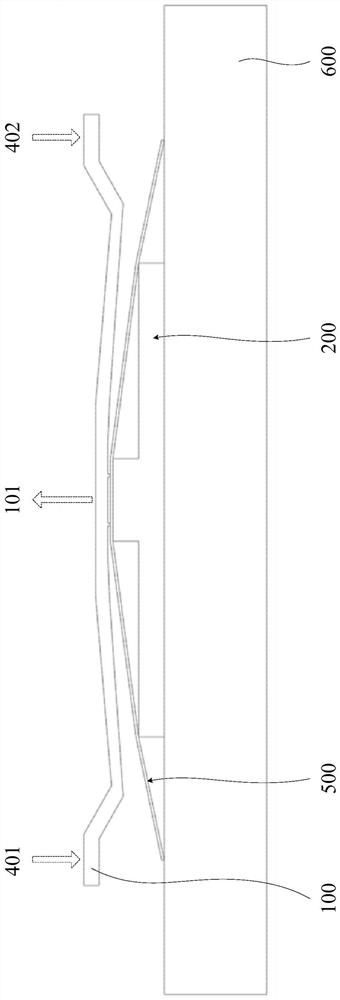
technical field [0001] This application relates to film bonding technology, in particular to film bonding press plate jigs, lamination structures and film bonding devices. Background technique [0002] In the production process of film bonding, two pressing plates are used as jigs to press and fix the film. Both sides of the upper pressing plate are installed on the fixed structure and fixed by positioning parts, and the lower pressing plate is directly placed on the working platform. Such as figure 1 As shown, in the film bonding device, the lower pressing plate 600 with the pressing position 200 is fixed on the working platform, and the working platform can also be called a machine table. Between 100, the pressing positions on both sides of the upper platen 100 are respectively fixed on the fixed structure 400 by the positioning pieces 300. The positioning pieces 300 in the film bonding device can use positioning beads, and the fixed structure 400 is the upper platen pos...

Claims


Application Information

Patent Timeline
IPC IPC(8): B29C65/56B29L7/00
CPCB29C65/56B29L2007/008
Inventor 吴俊翰
Owner INTERFACE TECH CHENGDU CO LTD
Learn More