Flame-retardant fireproof door

A fire-resistant door and flame-retardant technology, applied in the field of fire-resistant doors, can solve the problems of prolonging the opening time, poor sound insulation effect, increasing burns, etc., so as to avoid wasting time opening the door, increase the possibility of escape, and hinder the fire The effect of the spread

Inactive Publication Date: 2021-04-30
斯燕方
View PDF0 Cites 0 Cited by
  • Summary
  • Abstract
  • Description
  • Claims
  • Application Information

AI Technical Summary

Problems solved by technology

[0003] However, existing normally closed fire doors still have certain defects in use, especially the normally closed fire doors used in some special environments, such as when the fire is fierce, the door handle and the door become hot due to the fire, and the survivors When opening the door, the opening time will be extended, which will shorten the favorable time for escape and increase the risk of burns. This type of normally closed fire door is often coated with fire-resistant paint on the door panel when it is used, so as to achieve the purpose of fire prevention. On the one hand, it is neglected that in the event of a fire, the door and the door handle will become hot due to the fire, and the survivors cannot open the fire door to escape smoothly. When the fire is large, open an escape channel for the survivors. When a fire breaks out, it is not convenient for the survivors to escape. Secondly, when there is no fire in daily use, it is difficult to open this kind of fire door, and it is easy to damage the door frame due to the humid environment. There is rust between the door and the door panel, which makes it difficult to open it manually. Because of the use of fire-resistant coatings, there are often gaps when opening or closing, resulting in poor sound insulation. For this reason, we propose a flame-retardant type Fire doors are used to solve the above problems

Method used


Image

  • Flame-retardant fireproof door
  • Flame-retardant fireproof door
  • Flame-retardant fireproof door

Examples


Embodiment Construction

[0025] In order to make the technical means, creative features, goals and effects achieved by the present invention easy to understand, the present invention will be further described below in conjunction with specific embodiments.

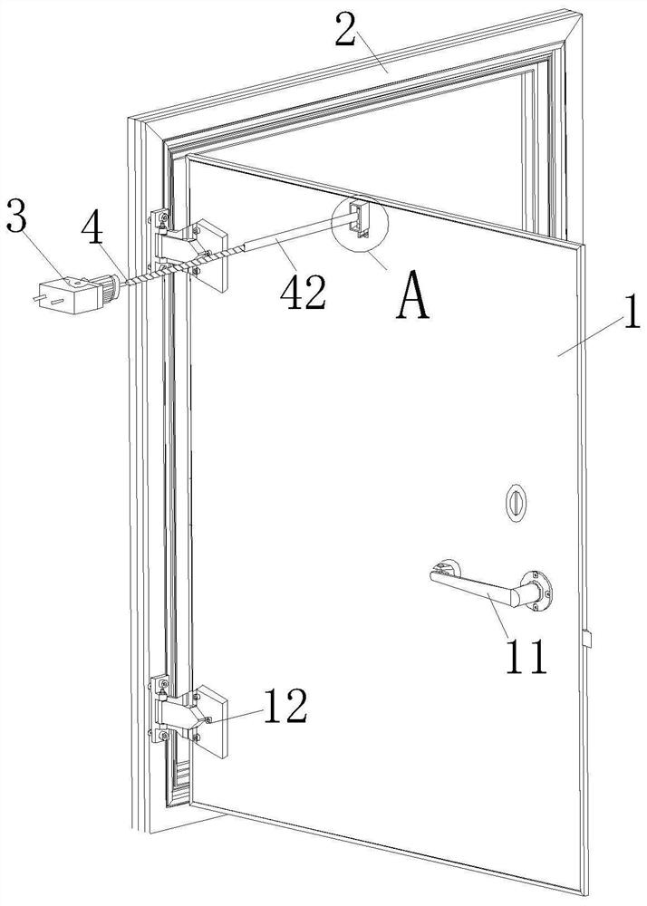
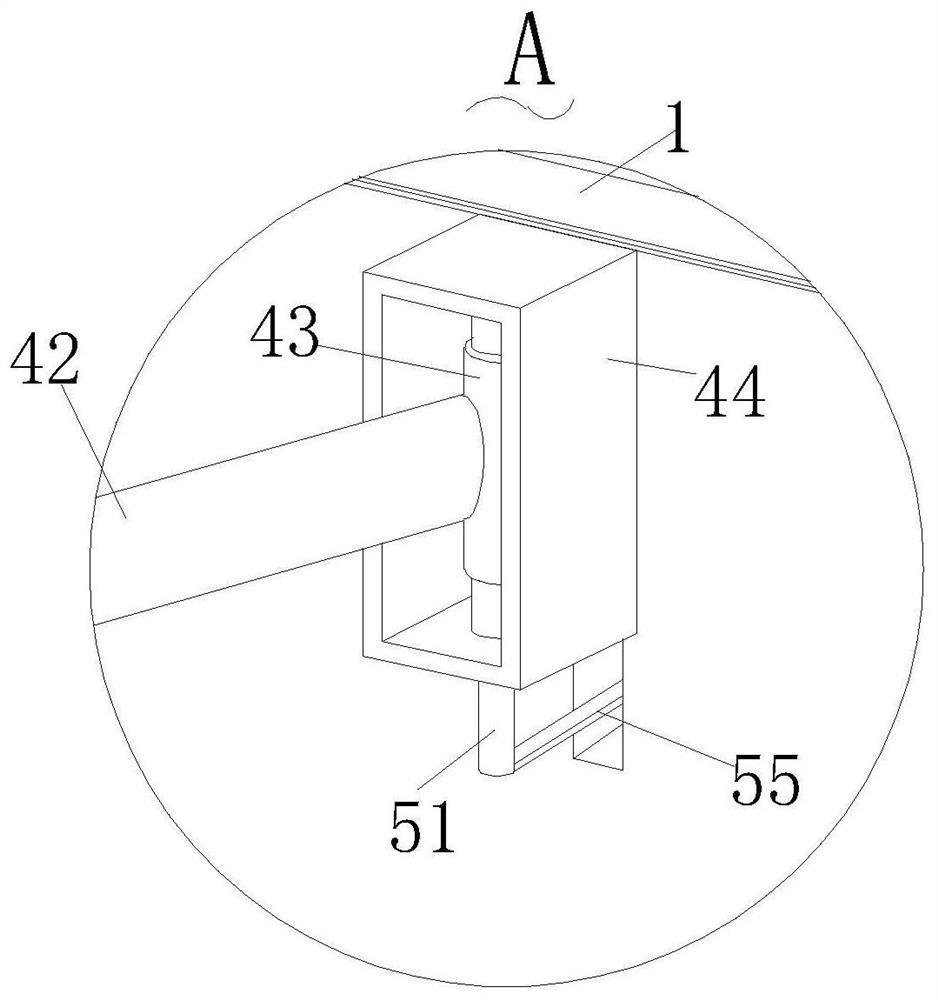
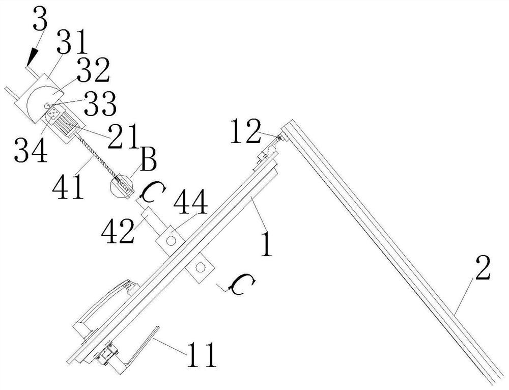
[0026] Such as Figure 1-Figure 8As shown, a flame-retardant fire door according to the present invention includes a door panel 1, a door frame 2, a handle 11 and a hinge 12 constituting a fire door. The inside four sides of the door panel 1 are fixed with sealing plates 13, and the inside of the sealing plate 13 is close to The top position is fixedly connected with a fixed frame 16, and the central position of the fixed frame 16 is fixedly connected with a U-shaped frame 161 and a U-shaped column 162. The U-shaped column 162 is located inside the U-shaped frame 161, and the U-shaped frame 161 is fixed on the door panel. 1, the inside of the door panel 1 is divided into a first chamber 14 and a second chamber 15 by a sealing plate 13 and a fixing...


PUM


Abstract

The invention relates to the field of fireproof doors, and particularly relates to a flame-retardant fireproof door. The flame-retardant fireproof door comprises a door plate, a door frame, a handle and a hinge which form the fireproof door, wherein a pressurizing assembly is fixedly mounted in the center of the top of the door plate and fixedly connected with an output shaft of a motor, the motor is fixedly connected with a fixing assembly, the fixing assembly is fixed on a wall, a blocking assembly is arranged in the center of the top of the door plate, an outlet of the pressurizing assembly is blocked by the blocking assembly in a sleeving manner, and a switch assembly is fixed on the side edge of a U-shaped column. The problems that when an existing normally closed fireproof door is used, particularly when a fire occurs and the fire is fierce, the door is difficult to open, on one hand, the situation that the door becomes hot due to the fire when the fire occurs is ignored, and survivors cannot smoothly open the fireproof door for escape, and on the other hand, the fireproof door can only prevent the door plate from fire within a certain period of time and cannot open an escape channel for the survivors when the fire is fierce can be solved.

Description

technical field [0001] The invention relates to the field of fire doors, in particular to a flame-retardant fire door. Background technique [0002] Fire doors refer to doors that can meet the requirements of fire resistance stability, integrity and heat insulation within a certain period of time. Fire doors are divided into three types: normally open fire doors, normally closed fire doors and movable fire doors according to their usual opening status. Among them, the normally closed fire doors are closed at ordinary times and opened in the event of a fire, and most of them are made of steel materials. [0003] However, existing normally closed fire doors still have certain defects in use, especially the normally closed fire doors used in some special environments, such as when the fire is fierce, the door handle and the door become hot due to the fire, and the survivors When opening the door, the opening time will be extended, which will shorten the favorable time for esca...

Claims


Application Information

Patent Timeline
Patent Type & Authority Applications(China)
IPC IPC(8): E06B5/16E05F15/72E05F15/622E06B7/28A62C31/02A62C37/10
CPCA62C31/02A62C37/10E06B5/16E06B7/28E05F15/622E05F15/72
Inventor 斯燕方何莹
Owner 斯燕方
Why Eureka
Try Eureka