Aircraft control surface deflection angle measuring method

A rudder surface deflection and angle measurement technology, which is used in aircraft component testing, measuring devices, measuring angles, etc., can solve the problems of manual reading error, low work efficiency, poor fixing effect, etc., and achieves high accuracy, easy operation, and practicality. sexual effect

Active Publication Date: 2021-04-30
CHENGDU AIRCRAFT INDUSTRY GROUP
View PDF5 Cites 10 Cited by
  • Summary
  • Abstract
  • Description
  • Claims
  • Application Information

AI Technical Summary

Problems solved by technology

[0002] The known rudder surface angle measurement method is mainly to place the deflection rudder surface by means of a mechanical protractor, and the pointer is always vertically downward due to the effect of gravity. When the rudder surface is deflected, the deflection angle of the pointer is the rudder surface deflection angle, but The measurement principle of the mechanical protractor is based on the principle of the plumb line. When reading the angle, it is necessary to wait for the angle pointer to stabilize before reading. The work efficiency is low, and errors are prone to occur in manual readings. The degree of firmness is fixed, the operation is troublesome and the fixing effect is poor

Method used


Image

  • Aircraft control surface deflection angle measuring method
  • Aircraft control surface deflection angle measuring method
  • Aircraft control surface deflection angle measuring method

Examples


Embodiment 1

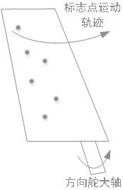
[0053] A method for measuring the deflection angle of an aircraft rudder surface, such as Figure 1-Figure 3 As shown, the marker points are pasted on the rudder surface of the aircraft and other parts, and the motion space trajectory of the marker points pasted on the aircraft rudder surface is measured by an industrial photogrammetry camera, and the rudder The spatial coordinates of the marker points on the surface in each state, and simulate the movement trajectory of the marker points, determine the rotation axis of the aircraft rudder surface, and make a vertical line from the marker points in each deflection state to the rudder surface rotation axis, and a single marker point The angle between the vertical lines in different states is the deflection angle of the aircraft rudder surface.

[0054]The invention can realize the real-time display of the change amount of the deflection angle of the rudder surface. Compared with the mechanical protractor, the advantage is that ...

Embodiment 2

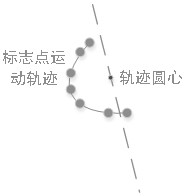
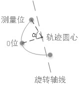
[0056] This embodiment is optimized on the basis of embodiment 1, such as image 3 As shown, when the rudder surface is at zero position, use the camera to measure the spatial position of each marker point, record the spatial position information of the marker point, and control the rotation angle of the rudder surface to obtain n observation values ​​of a certain marker point. According to the observation value, the movement The trajectory is simulated, and the center of circle O and the rudder angle α are fitted according to the geometric relationship; the rotation plane where the observation point is fitted is fitted, and the coordinates of the projection points from the coordinates of all observations to the rotation plane are calculated, and the circle is carried out according to the projection points in the selected plane. Arc trajectory fitting.

[0057] Further, when fitting the rotating plane, all observations of the measurement points are substituted into the plane e...

Embodiment 3

[0097] A method for measuring the deflection angle of an aircraft rudder surface, such as figure 1 As shown, the motion space trajectory of the marker points pasted on the aircraft rudder surface is measured by an industrial photogrammetry camera, the rotation axis of the aircraft rudder surface is determined, and the vertical line from the marker points in each deflection state to the rudder surface rotation axis is made. A single marker The angle between the vertical lines under different states is the deflection angle of the aircraft rudder surface.

[0098] Place the industrial photography camera 4-7 meters away from the aircraft control surface to ensure that the two cameras have an intersection field of view, ensure that the intersection field of view completely covers the aircraft control surface, and ensure that the standard point can be observed by the camera on the movement route; run industrial photography system, establish a digital space measurement field; paste t...


PUM


Abstract

The invention discloses an aircraft control surface deflection angle measuring method. The method comprises the following steps of pasting mark points on an aircraft control surface and other parts, measuring the motion space track of the mark points pasted on the aircraft control surface by using an industrial photogrammetric camera, and taking the mark points of other parts of an aircraft as reference points; and obtaining space coordinates of the mark points on the control surface in each state, simulating the motion tracks of the mark points, determining the rotation axis of the aircraft control surface, drawing a vertical line from the mark points to the rotation axis of the control surface in each deflection state, and taking the included angle of the vertical line of a single mark point in different states as the deflection angle of the aircraft control surface. According to the invention, the variable quantity of the deflection angle of the control surface can be displayed in real time, the problems of complicated tool fixation, poor universality, low angle measurement precision and the like of the original measurement method are solved, the credibility of measurement data is improved, and the method has the advantages of intuitive and convenient measurement result reading, high precision and easiness in operation.

Description

technical field [0001] The invention belongs to the technical field of angle measurement, and in particular relates to a method for measuring the deflection angle of an aircraft rudder surface. Background technique [0002] The known rudder surface angle measurement method is mainly to place the deflection rudder surface by means of a mechanical protractor, and the pointer is always vertically downward due to the effect of gravity. When the rudder surface is deflected, the deflection angle of the pointer is the rudder surface deflection angle, but The measurement principle of the mechanical protractor is based on the principle of the plumb line. When reading the angle, it is necessary to wait for the angle pointer to stabilize before reading. The work efficiency is low, and errors are prone to occur in manual readings. The firmness is fixed, the operation is troublesome and the fixing effect is poor. Contents of the invention [0003] The object of the present invention i...

Claims


Application Information

Patent Timeline
Patent Type & Authority Applications(China)
IPC IPC(8): G01C1/00B64F5/60
CPCG01C1/00B64F5/60
Inventor 郑博谢云后柏宇赵佩倪城刘洋志丁国平张永建
Owner CHENGDU AIRCRAFT INDUSTRY GROUP
Why Eureka
Try Eureka