
Wafer detection device

A detection device and wafer technology, applied in the direction of measuring devices, mechanical measuring devices, mechanical devices, etc., can solve problems such as low operation efficiency, difficult operation, and wafer drop

Inactive Publication Date: 2021-04-30
湖南三安半导体有限责任公司
View PDF18 Cites 0 Cited by
  • Summary
  • Abstract
  • Description
  • Claims
  • Application Information

AI Technical Summary

Problems solved by technology

[0003] This inspection method needs to be inspected under incandescent lamps, which has great requirements on the operator's action specifications and operating techniques. If the size of the wafer is slightly larger, the manual inspection operation will be more difficult and prone to inspection problems. Low working efficiency due to problems such as wafer drop and missed defect detection

Method used


Image

  • Wafer detection device
  • Wafer detection device
  • Wafer detection device

Examples


Embodiment Construction

[0024] In order to make the purpose, technical solutions and advantages of the embodiments of the present invention clearer, the technical solutions in the embodiments of the present invention will be clearly and completely described below in conjunction with the drawings in the embodiments of the present invention. Obviously, the described embodiments It is a part of embodiments of the present invention, but not all embodiments. The components of the embodiments of the invention generally described and illustrated in the figures herein may be arranged and designed in a variety of different configurations.

[0025] Accordingly, the following detailed description of the embodiments of the invention provided in the accompanying drawings is not intended to limit the scope of the claimed invention, but merely represents selected embodiments of the invention. Based on the embodiments of the present invention, all other embodiments obtained by persons of ordinary skill in the art wi...


PUM


Abstract

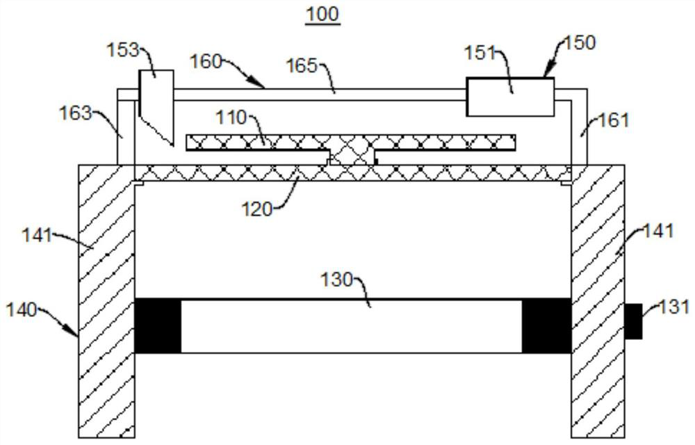
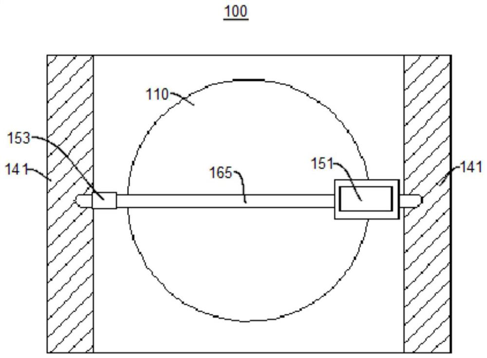
The invention discloses a wafer detection device, and relates to the technical field of semiconductors. The wafer detection device comprises an object carrying disc, a light transmitting plate, a light source and a measuring instrument, the object carrying disc is rotatably arranged on the light transmitting plate, and the object carrying disc is used for placing a wafer to be detected; the light source is arranged on one side, far away from the carrying disc, of the light-transmitting plate, so that light emitted by the light source can penetrate through the light-transmitting plate to irradiate the to-be-detected wafer, and whether the to-be-detected wafer has defects or not can be detected; and the measuring instrument is arranged at one side, far away from the light-transmitting plate, of the carrying disc and is used for measuring the size of the to-be-measured wafer. The wafer detection device can conveniently and quickly detect the appearance defects and sizes of the wafers, and is convenient to detect and high in efficiency.

Description

technical field [0001] The present invention relates to the technical field of semiconductors, in particular to a wafer detection device. Background technique [0002] At present, the existing silicon carbide wafer inspection method is to cut the silicon carbide wire slices and place them on the plug according to the cutting sequence, and the inspectors will take out the wafers for appearance inspection, and visually inspect them under incandescent light. Or use a flashlight to irradiate the wire-cut wafers to observe whether there are defects such as missing corners or cracks or other abnormalities, and select and isolate the wafers with defects or abnormalities. [0003] This inspection method needs to be inspected under incandescent lamps, which has great requirements on the operator's action specifications and operating techniques. If the size of the wafer is slightly larger, the manual inspection operation will be more difficult and prone to inspection problems. Wafer ...

Claims


Application Information

Patent Timeline
IPC IPC(8): G01N21/01G01N21/95G01B5/02
CPCG01N21/01G01N21/9505G01B5/02
Inventor 蔡少忠张洁张煌珊林艺鸿杨艺松
Owner 湖南三安半导体有限责任公司
Learn More