CT front collimator and manufacturing method thereof
A technology of a front collimator and a manufacturing method, which is applied in the field of ray CT systems, can solve the problems that a detector cannot effectively filter invalid rays, a detector has a low signal-to-noise ratio, and the like
- Summary
- Abstract
- Description
- Claims
- Application Information
AI Technical Summary
Problems solved by technology
Method used
Image

Examples
Embodiment 1
[0044] In view of the above, an embodiment of the present invention, such as Figure 1 to Figure 3 As shown, a method for manufacturing a CT front collimator is disclosed, comprising the following steps:
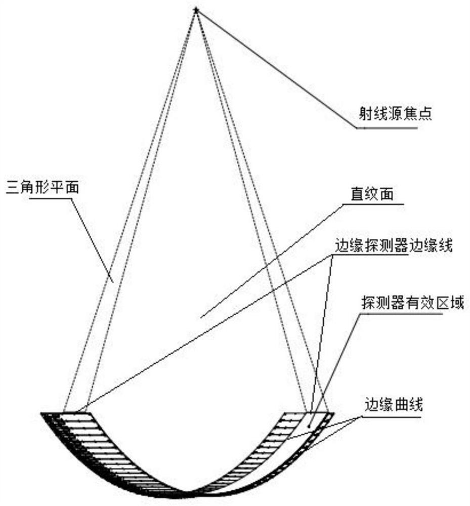
[0045] Step 1: Determine the shape of the front collimator slit:
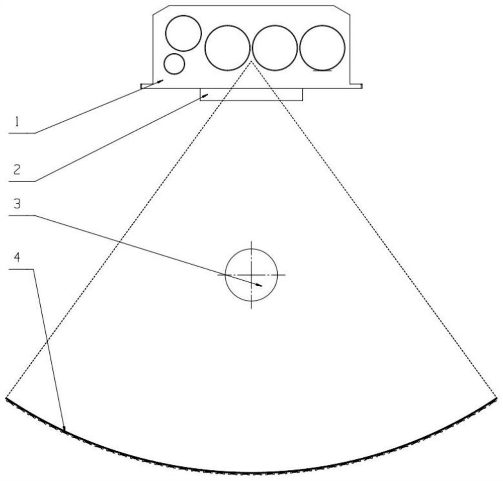
[0046] In the CT detection device, the rays emitted by the ray source 1 are cone beams or cone fan beams, and the apex of the cone is the focus of the ray source; the detector group 4 is a group of detectors formed by a plurality of detectors in one or more rows, such as figure 1 shown. In the current CT detection device, in order to reduce the overall size of the equipment and make the magnification ratio of the object under test consistent, the detector group 4 is usually arranged in a multi-row arc along the rotation direction and the center of the circle points to the ray source 1, and the object under test 3 is located at the center of circle.
[0047] The detector includes a crystal part and a circui...
Embodiment 2
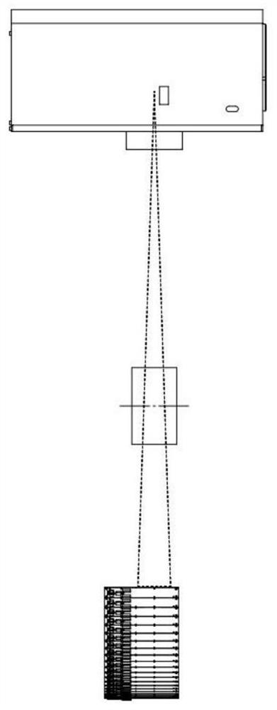
[0054] An embodiment of the present invention, such as Figure 4 to Figure 6 As shown, a CT front collimator is disclosed, the slit of the front collimator is formed by two curves, and the shape of the curves is determined according to the manufacturing method in Embodiment 1.
[0055] In the embodiment of the present invention, the front collimator is made of heavy metal material, so that the front collimator can block redundant rays and only allow effective rays to pass through. Preferably, the front collimator is made of lead or tungsten.
[0056] In the embodiment of the present invention, within the height range of the entire front collimator (Y direction), the two long sides of the front collimator slit are formed by the two curves described in Embodiment 1 on each XZ plane, also That is to say, the shape of the slit of the front collimator is consistent with the shape of the effective rays, so that the rays entering the front collimator can completely pass through the ...
Embodiment 3
[0062] An embodiment of the present invention, such as Figure 7 to Figure 8 As shown, another CT front collimator is disclosed, the slit of the front collimator is formed by two curves, and the shape of the curves is determined according to the manufacturing method in Embodiment 1.
[0063] The front collimator of the embodiment of the present invention includes four rectangular side plates and a rectangular bottom plate. The four side plates are parallel to each other to form a box with one side open. The bottom plate is provided with a slit along the height direction, and the slit is on the XY plane. The projection is a rectangle.
[0064] When in use, the open side of the front collimator is arranged facing the radiation source 1 , and the bottom plate is arranged facing the detector group 4 . The rays enter the front collimator from the opening, pass through the gap on the bottom plate, and are received by the detector group 4 . After the rays irradiate the front collim...
PUM
 Abstract
Description
Claims
Application Information
 - R&D
- Intellectual Property
- Life Sciences
- Materials
- Tech Scout
- Unparalleled Data Quality
- Higher Quality Content
- 60% Fewer Hallucinations
Browse by: Latest US Patents, China's latest patents, Technical Efficacy Thesaurus, Application Domain, Technology Topic, Popular Technical Reports.
© 2025 PatSnap. All rights reserved.Legal|Privacy policy|Modern Slavery Act Transparency Statement|Sitemap|About US| Contact US: help@patsnap.com