Method and device for determining aerial photography triggering point

A technology for determining methods and trigger points, applied in the field of visual inspection, can solve the problems of complex debugging process, unknown overall time delay, and labor-intensive problems

Active Publication Date: 2021-04-30
CHANGZHOU MICROINTELLIGENCE CO LTD
View PDF8 Cites 3 Cited by
  • Summary
  • Abstract
  • Description
  • Claims
  • Application Information

AI Technical Summary

Problems solved by technology

Since the overall time delay of the camera and the system is unknown, it is difficult to determine the position advance of the camera triggering the shooting signal
If you use a manual method to find this lead, it will take a lot of manpower due to the complexity of the debugging process

Method used


Image

  • Method and device for determining aerial photography triggering point
  • Method and device for determining aerial photography triggering point
  • Method and device for determining aerial photography triggering point

Examples


Embodiment Construction

[0025] The following will clearly and completely describe the technical solutions in the embodiments of the present invention with reference to the accompanying drawings in the embodiments of the present invention. Obviously, the described embodiments are only some, not all, embodiments of the present invention. Based on the embodiments of the present invention, all other embodiments obtained by persons of ordinary skill in the art without making creative efforts belong to the protection scope of the present invention.

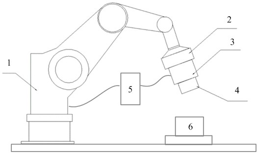
[0026] Such as figure 1 As shown, the flying shooting device in the embodiment of the present invention may include a robot arm 1 and a camera bracket 2, a camera 3, and a light source 4 arranged at the end of the robot arm 1, and includes an operating The calculation machine 5 of the control program. The mechanical arm 1, the camera bracket 2, the camera 3 and the light source 4 can be arranged corresponding to the platform 6 on which the object to be photog...


PUM


Abstract

The invention provides a method and a device for determining an aerial photography trigger point. The method comprises the following steps: S1, constructing a reinforcement learning network; S2, training the reinforcement learning network by taking images shot by aerial photography equipment in a plurality of aerial photography states as training data to obtain an aerial photography control model, wherein each aerial photography state has a corresponding photography triggering point; and S3, determining an actual photography triggering point through the aerial photography control model. According to the invention, the photography triggering point of the camera in the photography process can be determined automatically, quickly and accurately, so that a high-quality to-be-detected workpiece image can be obtained quickly and efficiently.

Description

technical field [0001] The present invention relates to the technical field of visual detection, and in particular to a method for determining a trigger point of a flying camera, a device for determining a trigger point of a flying camera, a computer device, and a non-transitory computer-readable storage medium. Background technique [0002] In the traditional process of using industrial cameras for visual inspection, the industrial cameras are fixed at the end of the robotic arm. When the workpiece to be inspected is transported to the shooting position, the robotic arm moves the camera to the shooting point of the workpiece, stops the motion and takes a static shot. Next, in the same way, the robotic arm carries the camera to take a static shot of the next point until all the positions to be shot are shot. In this process, the industrial camera needs to stop moving every time it reaches the shooting point, resulting in a long shooting cycle and low efficiency. [0003] In...

Claims


Application Information

Patent Timeline
Patent Type & Authority Applications(China)
IPC IPC(8): G06T7/00G06N3/08H04N5/232
CPCG06T7/0004G06N3/08G06T2207/20081G06T2207/20084G06T2207/30164H04N23/64
Inventor 顾徐波王闯马元巍赵威峰潘正颐侯大为
Owner CHANGZHOU MICROINTELLIGENCE CO LTD
Why Eureka
Try Eureka