Eureka AIR delivers breakthrough ideas for toughest innovation challenges, trusted by R&D personnel around the world.

Chemical preparation container cleaning device

A cleaning device and chemical technology, applied in the field of chemicals, can solve the problems of unfavorable container handling and storage, bloated container volume, cumbersome use steps, etc., and achieve the effects of convenient handling and storage, good cleaning effect, and reduced operation difficulty

Active Publication Date: 2021-05-04
江西瑞思博新材料有限公司
View PDF7 Cites 1 Cited by
  • Summary
  • Abstract
  • Description
  • Claims
  • Application Information

AI Technical Summary

Problems solved by technology

[0003] The existing patent number CN104998867B proposes a pressure vessel cleaning device, which has the advantages of conveniently filtering the cleaning water through a filter screen, thereby facilitating and quickly cleaning the pressure vessel, but the above-mentioned device must be fixed on the container, resulting in a bloated container And the weight increases, which is not conducive to operations such as container handling and storage, and causes the cost of the container to increase
[0004] The existing patent No. CN103687678A proposes a container cleaner, which has the spray angle of the nozzle and can guide the water to all the internal parts of the container, thereby effectively cleaning the container. Inconvenient problem, and if additional fixing devices are used, a certain amount of disassembly and assembly operations are required, and the use steps are cumbersome, resulting in low cleaning efficiency

Method used


Image

  • Chemical preparation container cleaning device
  • Chemical preparation container cleaning device
  • Chemical preparation container cleaning device

Examples


Embodiment Construction

[0038]Next, the technical solutions in the embodiments of the present invention will be apparent from the embodiment of the present invention, and it is clearly described, and it is understood that the described embodiments are merely embodiments of the present invention, not all of the embodiments. Based on the embodiments of the present invention, there are all other embodiments obtained without making creative labor without making creative labor premises.

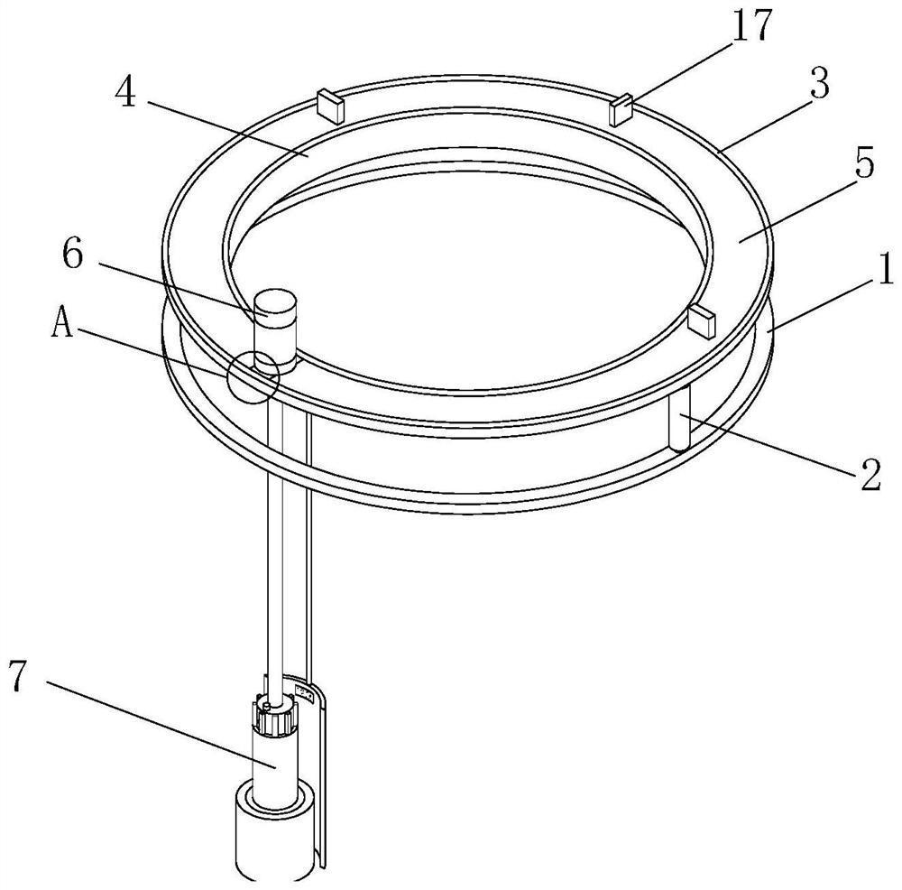
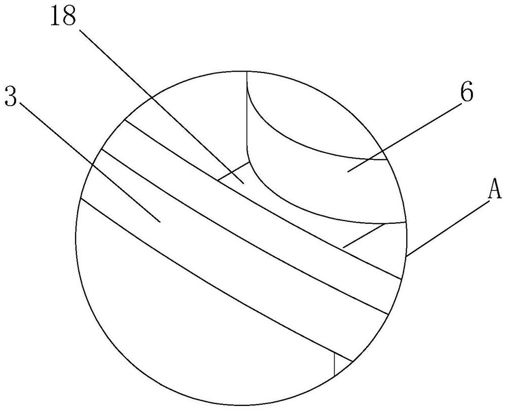
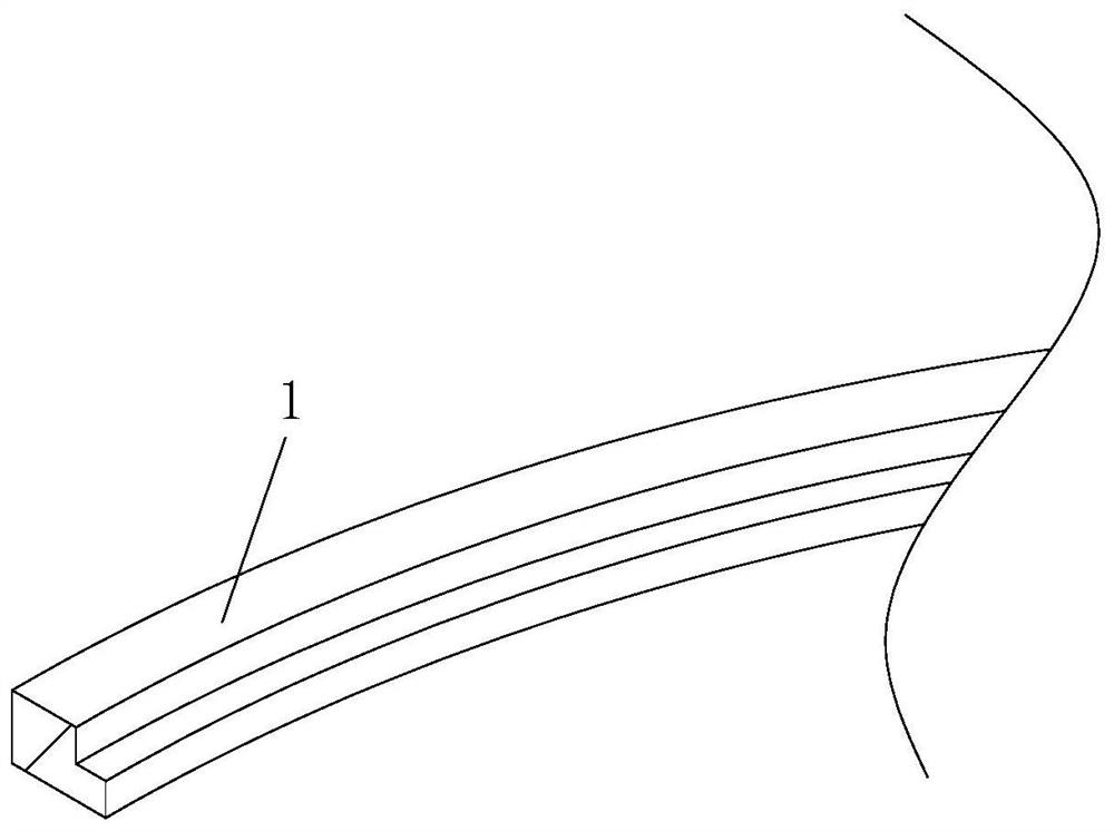
[0039]SeeFigure 1-7, A chemical prepared container cleaning device, including a fixed ring 1, an annular groove having an annular groove in the inner wall of the fixed ring 1, and both sides of the fixed ring 1 are provided with a telescopic mechanism 2, and the transmission shaft of the telescoping mechanism 2. The connection is fixed to the top surface of the fixed ring, and the telescopic mechanism 2 is fixed to the top surface of the telescopic mechanism 2, and the connecting ring A3 is fixed, and the inner wall of the connec...


PUM


Abstract

The invention relates to the technical field of chemicals, and discloses a chemical preparation container cleaning device which comprises a fixing ring, wherein an annular groove is sectioned in the bottom end of the inner wall of the fixing ring, telescopic mechanisms are arranged on the top surfaces of two sides of the fixing ring correspondingly, transmission shafts of the telescopic mechanisms are fixedly connected with the top surface of the fixing ring, and connecting rings A are fixedly connected to the top surfaces of the telescopic mechanisms; an annular groove is formed in the inner wall of the connecting ring A, a rotating ring sleeves the annular groove in the inner wall of the connecting ring A, the cross section of the rotating ring is in a cross shape, a connecting ring B sleeves the outer wall of the inner ring of the rotating ring, and an annular groove is formed in the outer wall of the connecting ring B. A rotating motor is arranged on the left side of the top surface of the rotating ring, and a transmission shaft of the rotating motor penetrates through the rotating ring and is fixedly provided with a cleaning mechanism. By arranging the fixing ring, disassembly and assembly on the chemical preparation container can be achieved through simplest operation, so that the cleaning efficiency is improved. The size and weight of the chemical preparation container cannot be increased after disassembly, so that it is favorable to carry and store the chemical preparation container.

Description

Technical field[0001]The present invention relates to the field of chemical technology, in particular a chemical preparation container cleaning device.Background technique[0002]During the preparation of chemicals, the chemicals are needed to be added to the container, which can be referred to as chemical preparation vessels. After the chemical preparation is completed and taken out, the chemical preparation container needs to avoid pollution. Convenient follow-up and stored, it is necessary to use the corresponding cleaning device.[0003]The existing patent number proposes that CN104998867B proposes a pressure vessel cleaning device, which is provided to filter the cleaning water by the filter, thereby facilitating the rapid cleaning of the pressure vessel, but the above device must be fixed in the container, resulting in a container volume bloated And the weight is increased, which is not conducive to the operation of container handling and storage, and the cost of the container is ...

Claims


Application Information

Patent Timeline
Patent Type & Authority Applications(China)
IPC IPC(8): B08B9/087B08B9/08B08B13/00G01N19/08
CPCB08B9/087B08B9/08B08B13/00G01N19/08
Inventor 邱龙
Owner 江西瑞思博新材料有限公司
Why Eureka
Eureka Blog
Learn More