
Welding protection device for semi-closed to-be-welded piece

A semi-closed, protective device technology, used in welding accessories, devices for supplying/removing protective gas, etc., which can solve the problems of uneven annular welds, valve body accuracy, poor use stability and cleanliness.

Active Publication Date: 2021-05-04
BEIJING SEVENSTAR FLOW CO LTD
View PDF6 Cites 0 Cited by
  • Summary
  • Abstract
  • Description
  • Claims
  • Application Information

AI Technical Summary

Problems solved by technology

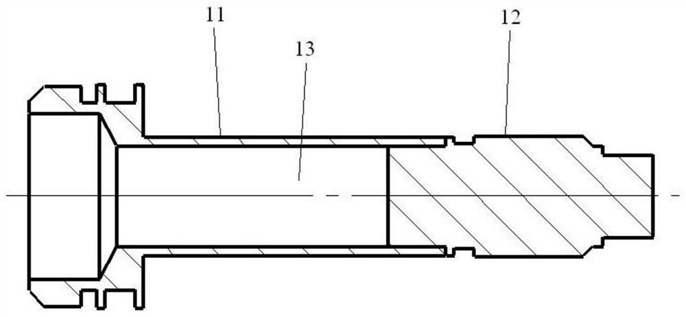
[0003] like figure 1 As shown, an existing valve body applied to a mass flow controller includes a valve seat 11 and a stud head 12, wherein the valve seat 11 is provided with a channel 13 passing through itself, and the stud head 12 passes through one end of the channel 13. Close fit, close one end of the channel 13 to semi-close the channel 13, so that a semi-closed inner cavity is formed in the valve body. This kind of semi-closed valve body also needs to weld the valve seat 11 and the stud head 12 during production, usually using The way of argon arc welding is to isolate the air with argon gas to avoid oxidation on the outside of the welding place between the valve seat 11 and the stud head 12. However, when the valve seat 11 and the stud head 12 are welded, due to the The inner side of the weld is not protected, so there will be welding impurities in the channel 13 of the valve seat 11, the metallographic phase of the inner side of the weld between the valve seat 11 and the stud head 12 will change, and the weld between the valve seat 11 and the stud head 12 will The circular weld seam is uneven, resulting in poor precision, stability and cleanliness of the valve body

Method used


Image

  • Welding protection device for semi-closed to-be-welded piece
  • Welding protection device for semi-closed to-be-welded piece
  • Welding protection device for semi-closed to-be-welded piece

Examples


Embodiment Construction

[0029] In order for those skilled in the art to better understand the technical solution of the present invention, the semi-enclosed welding protection device for parts to be welded provided by the present invention will be described in detail below in conjunction with the accompanying drawings.

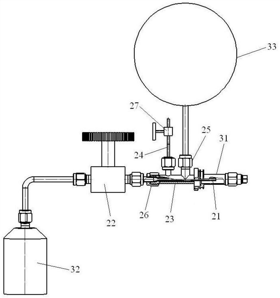
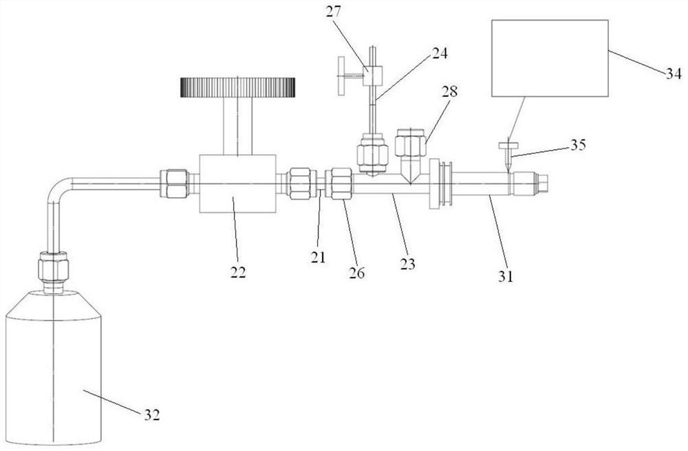
[0030] Such as figure 2 As shown, this embodiment provides a semi-enclosed welding protection device for the part 31 to be welded, including a gas delivery pipe 21, a first adjustment part 22 and a return pressure holding assembly, wherein one end of the gas delivery pipe 21 is passed through the first adjustment The component 22 communicates with the shielding gas source 32 for providing shielding gas, and the other end passes through the return pressure holding assembly, and extends into the semi-closed inner cavity of the semi-closed part 31 to be welded to deliver the shielding gas into the semi-closed interior cavity; the first regulating part 22 is used to adjust the flow rate...


PUM


Abstract

The invention provides a welding protection device for a semi-closed to-be-welded piece. The welding protection device comprises a gas delivering pipe fitting, a first adjusting component and a backflow pressure maintaining assembly. One end of the gas delivering pipe fitting communicates with a protection gas source used for providing protection gas through the first adjusting component, and the other end of the gas delivering pipe fitting penetrates through the backflow pressure maintaining assembly and stretches into a semi-closed inner cavity of the semi-closed to-be-welded piece to deliver the protection gas into the semi-closed inner cavity. The first adjusting component is used for adjusting the flow of the protection gas provided by the protection gas source. The backflow pressure maintaining assembly communicates with the atmosphere and the semi-closed inner cavity respectively, the protection gas entering the semi-closed inner cavity can flow back into the semi-closed inner cavity, and internal pressure is formed in the semi-closed inner cavity. The backflow pressure maintaining assembly is further used for communicating with a pressure measuring device capable of detecting the internal pressure. According to the provided welding protection device for the semi-closed to-be-welded piece, the precision, the usage stability and the cleanliness of the semi-closed to-be-welded piece after welding can be improved, and the welding yield of the semi-closed to-be-welded piece is increased.

Description

technical field [0001] The invention relates to the technical field of welding equipment, in particular to a semi-enclosed welding protection device for parts to be welded. Background technique [0002] Mass Flow Controller (MFC for short) is an instrument used to precisely measure and control the mass flow of fluids. It is widely used in various technical fields and plays an important role in the scientific research and production of these technical fields. It also puts forward more stringent requirements for the performance of mass flow controllers, especially for the accuracy, stability and cleanliness of mass flow controllers. Degree and other performance. [0003] Such as figure 1 As shown, an existing valve body applied to a mass flow controller includes a valve seat 11 and a stud head 12, wherein the valve seat 11 is provided with a channel 13 passing through itself, and the stud head 12 passes through one end of the channel 13. Close fit, close one end of the chan...

Claims


Application Information

Patent Timeline
IPC IPC(8): B23K9/32
CPCB23K9/325
Inventor 王传国
Owner BEIJING SEVENSTAR FLOW CO LTD
Learn More