Transmission device of single-blade lifting appliance and single-blade lifting appliance

A transmission, single-blade technology, applied in transmissions, fluid transmissions, transmission control, etc., can solve the problems of delays in hoisting operations of spreaders, discounts on brake positioning functions, and easy corrosion of hydraulic cylinder rods, so as to reduce failures. High speed, high positioning braking accuracy, easy maintenance and troubleshooting

Inactive Publication Date: 2021-05-04
SHANGHAI ELECTRIC WIND POWER GRP CO LTD
View PDF6 Cites 0 Cited by
  • Summary
  • Abstract
  • Description
  • Claims
  • Application Information

AI Technical Summary

Problems solved by technology

[0005] In order to ensure the full-angle rotation adjustment of the spreader, the hydraulic cylinder needs to have sufficient stroke. Due to the size limit of the hydraulic cylinder, the installation is mostly external installation. The hydraulic cylinder is exposed to the sea salt spray environment for a long time, and the hydraulic cylinder rod is easily corroded, resulting in damage to the seal. Oil leakage, which will cause the failure of the spreader to delay the hoisting operation, and the daily maintenance is inconvenient
[0006] If the hydraulic system leaks, the brake positioning function will be greatly reduced, leaving a safety hazard, and there is only one braking procedure. If the brake fails, there will be no emergency plan available

Method used


Image

  • Transmission device of single-blade lifting appliance and single-blade lifting appliance
  • Transmission device of single-blade lifting appliance and single-blade lifting appliance
  • Transmission device of single-blade lifting appliance and single-blade lifting appliance

Examples


Embodiment Construction

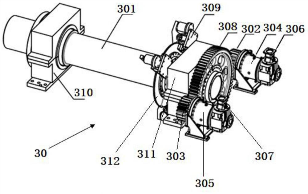
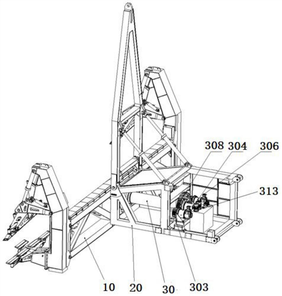
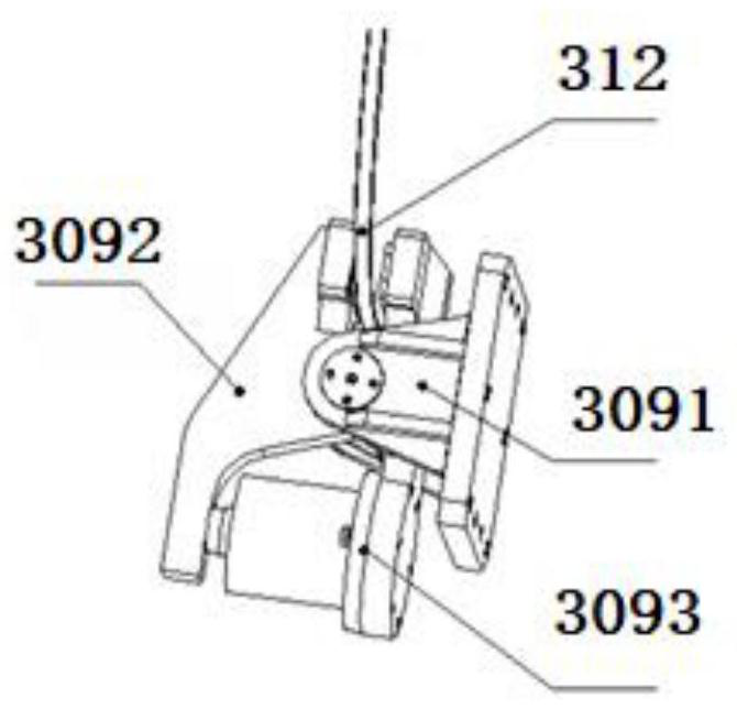
[0022] A single-blade spreader transmission device and a single-blade spreader proposed by the present invention will be further described in detail below in conjunction with the accompanying drawings and specific embodiments. The advantages and features of the present invention will become clearer from the following description. It should be noted that the drawings are in a very simplified form and all use imprecise scales, which are only used to facilitate and clearly assist the purpose of illustrating the embodiments of the present invention. In order to make the objects, features and advantages of the present invention more comprehensible, please refer to the accompanying drawings. It should be noted that the structures, proportions, sizes, etc. shown in the drawings attached to this specification are only used to match the content disclosed in the specification, for those who are familiar with this technology to understand and read, and are not used to limit the implement...


PUM


Abstract

The invention discloses a transmission device of a single-blade lifting appliance and the single-blade lifting appliance. The transmission device comprises a transmission assembly, a speed reducer, at least one hydraulic motor and a hydraulic valve group; the transmission assembly is arranged on a spindle of the single-blade lifting appliance; the input end of the speed reducer is connected with each hydraulic motor, and the output end of the speed reducer is connected with the transmission assembly; the hydraulic valve group is connected with an output shaft of each hydraulic motor; the output shaft of each hydraulic motor rotates clockwise or anticlockwise by switching the oil inlet direction or the oil return direction of a reversing valve in the hydraulic valve group, and the transmission assembly correspondingly drives the spindle to rotate, so that a lifting appliance main body of the single-blade lifting appliance rotates. The hidden danger of oil leakage of a hydraulic cylinder is eliminated, the failure rate is reduced, and maintenance is more convenient and faster.

Description

technical field [0001] The invention relates to the technical field of wind power, in particular to a single-blade spreader transmission device and a single-blade spreader. Background technique [0002] With the rapid development and maturity of wind power generation technology, different types of high-power (such as 6 MW, 8 MW, 10 MW) new models are constantly being launched, and the size of the blades of wind turbines is also gradually increasing. , so the hoisting process of wind turbines needs to be continuously improved to meet the reliability requirements of the actual hoisting process. [0003] In the existing full-angle rotary single-blade spreader, the driving form is mostly hydraulic cylinder, and the linear motion of the hydraulic cylinder is used to drive the main transmission shaft to realize the rotary motion. [0004] The blades need to be precisely positioned during installation, which requires the spreader to have the function of braking and positioning. Mo...

Claims


Application Information

Patent Timeline
Patent Type & Authority Applications(China)
IPC IPC(8): B66C1/12B66C13/08B66C13/14B66C13/20F16H47/02F16H61/4061F16H61/4157F03D13/10
CPCB66C1/12B66C13/08B66C13/14B66C13/20F16H47/02F16H61/4061F16H61/4157F03D13/10Y02E10/72
Inventor 刘磊刘吉辉李国松李浩文李沛文王建国蒋康华
Owner SHANGHAI ELECTRIC WIND POWER GRP CO LTD
Why Eureka
Try Eureka