Eureka AIR delivers breakthrough ideas for toughest innovation challenges, trusted by R&D personnel around the world.

Waterwheel oil cylinder for environmental sanitation machinery

An oil cylinder and mechanical technology, applied in the field of sanitation machinery water tanker oil cylinder, can solve the problems of no supporting heat dissipation measures, no protection measures for hydraulic rods, etc., and achieve the effects of reducing contact, protecting the working environment and reducing wear and tear.

Inactive Publication Date: 2021-05-04
XIANGTAN SANXING HYDRAULIC MACHINERY MFG
View PDF0 Cites 0 Cited by
  • Summary
  • Abstract
  • Description
  • Claims
  • Application Information

AI Technical Summary

Problems solved by technology

[0003] The purpose of the present invention is to provide a sanitation machine water wheel oil cylinder, to solve the problem that the hydraulic rod of the existing sanitation machine water wheel oil cylinder has no protection measures and no supporting heat dissipation measures proposed in the background technology

Method used


Image

  • Waterwheel oil cylinder for environmental sanitation machinery
  • Waterwheel oil cylinder for environmental sanitation machinery
  • Waterwheel oil cylinder for environmental sanitation machinery

Examples


Embodiment 1

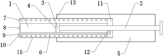
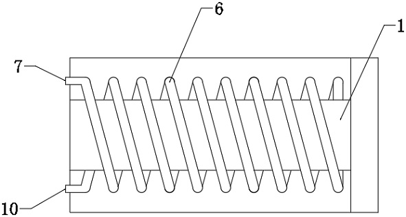
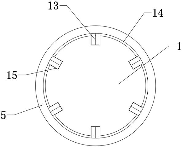
[0022] A sanitation mechanical water wheel oil cylinder, in order to facilitate heat dissipation and protect the hydraulic rod, as a preferred embodiment, such as figure 1 , figure 2 As shown, it includes cylinder body 1, hydraulic rod 2 and cylinder head 11. The top of oil cylinder body 1 is fixed with cylinder head 11 by bolts, the middle part of cylinder head 11 is provided with hydraulic rod 2, and the lower part of hydraulic rod 2 is fixed with piston 3 by bolts. The end of 3 is provided with shock absorbing device 4, the top of hydraulic rod 2 is welded with protective cover 5, protective cover 5 is cylindrical, and the inside of protective cover 5 is hollow structure, the bottom of protective cover 5 is provided with pulley 14, and the outside of oil cylinder body 1 is provided with The groove 15, the pulley 14 is slidingly connected with the groove 15, the lower oil inlet hole 8 is provided at the center of the bottom of the oil cylinder body 1, and the upper oil inle...


PUM


Abstract

The invention relates to the technical field of waterwheel oil cylinders, in particular to a waterwheel oil cylinder for environmental sanitation machinery. The waterwheel oil cylinder comprises an oil cylinder body, a hydraulic rod and a cylinder cover, wherein the cylinder cover is fixed to the top of the oil cylinder body through bolts, the hydraulic rod is arranged in the middle of the cylinder cover, a piston is fixed to the lower portion of the hydraulic rod through bolts, a damping device is arranged at the tail end of the piston, a protective sleeve is welded to the top end of the hydraulic rod, the protective sleeve is cylindrical, the interior of the protective sleeve is of a hollow structure, a lower oil inlet hole is formed in the center of the bottom of the oil cylinder body, an upper oil inlet hole is formed in the side face of the bottom of the oil cylinder body and connected with an oil outlet in the upper portion of the oil cylinder through a guide pipe, a circle of pipeline is arranged in the outer wall of the oil cylinder body in a surrounding mode, a water inlet and a water outlet are connected to the two ends of the pipeline and are both formed in the bottom of the oil cylinder body, a water tank of a waterwheel is connected into the water inlet through a guide pipe, water is introduced into the pipeline surrounding the interior of the oil cylinder body and discharged into the water tank of the waterwheel through the water outlet, heat is taken away through the flowing water, and heat dissipation of the oil cylinder is achieved.

Description

technical field [0001] The invention relates to the technical field of waterwheel oil cylinders, in particular to a sanitation machine waterwheel oil cylinder. Background technique [0002] The hydraulic rods of the existing sanitation machinery waterwheel cylinders have no protection measures, are easy to be contaminated with dust, and are easy to wear during work, and the existing sanitation machinery waterwheel cylinders have no matching heat dissipation measures, and the working time is too long, resulting in high temperature and easy damage . In view of this, we propose a sanitation mechanical waterwheel cylinder. Contents of the invention [0003] The object of the present invention is to provide a sanitation machinery waterwheel oil cylinder to solve the problem that the hydraulic rod of the existing sanitation machinery waterwheel oil cylinder has no protection measures and no matching heat dissipation measures proposed in the background technology. [0004] To a...

Claims


Application Information

Patent Timeline
Patent Type & Authority Applications(China)
IPC IPC(8): F15B15/17F15B15/20F15B15/22F15B21/041
CPCF15B15/1457F15B15/1485F15B15/17F15B15/226F15B21/041
Inventor 陈控
Owner XIANGTAN SANXING HYDRAULIC MACHINERY MFG
Why Eureka
Eureka Blog
Learn More