Chemical raw material crushing device

A technology for pulverizing device and chemical raw materials, applied in chemical instruments and methods, solid separation, sieving, etc., can solve the problems of crushing dead angle of the pulverizing device, affecting the processing quality of the pulverizing device, etc. simple effect

Pending Publication Date: 2021-05-07
梁淑平
View PDF11 Cites 4 Cited by
  • Summary
  • Abstract
  • Description
  • Claims
  • Application Information

AI Technical Summary

Problems solved by technology

[0004] However, when the crushing device is in use, the raw material is crushed through the mutual cooperation of the conical cylinder and the bevel gear, resulting in a crushing dead angle in the crushing device, which affects the processing quality of the crushing device

Method used


Image

  • Chemical raw material crushing device
  • Chemical raw material crushing device
  • Chemical raw material crushing device

Examples


Embodiment 1

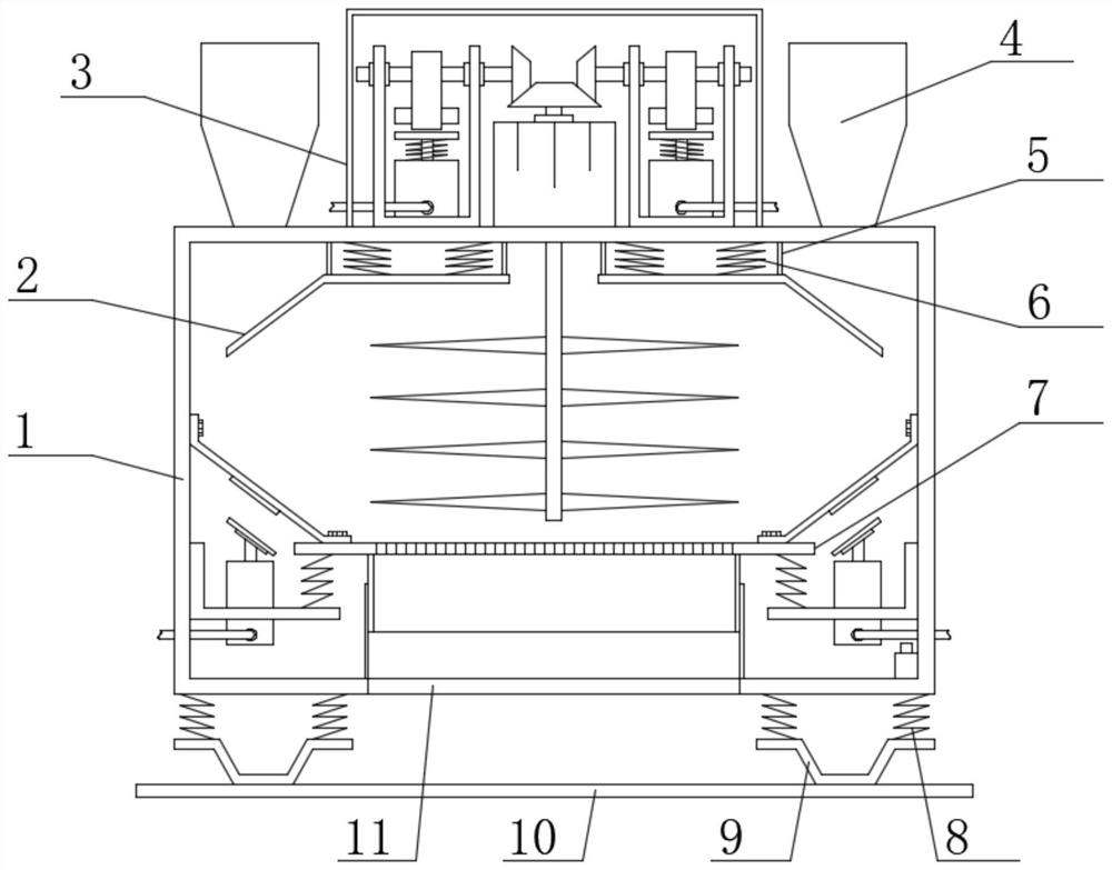
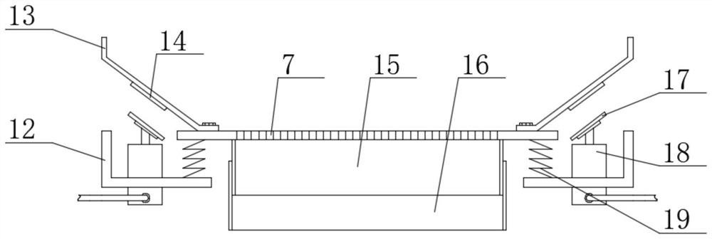
[0024] see Figure 1-Figure 4 , the present invention provides a technical solution: a chemical raw material crushing device, comprising a crushing box 1, the two ends of the upper surface of the crushing box 1 are fixedly connected with a lower hopper 4, and the middle part of the lower surface of the crushing box 1 is provided with a discharge through hole 11 , the bottom of the crushing box 1 is provided with a support base plate 10, the two ends of the upper surface of the support base plate 10 are fixedly connected with the limit support plate 9, and the top of the limit support plate 9 is fixedly connected with the second limit spring corresponding to the crush box 1 8. A metal screening plate 7 is arranged inside the crushing box 1, and the lower surface of the metal screening plate 7 is fixedly connected with a first flow guide tube 15 by welding, and the bottom end of the first flow guide tube 15 is slidingly connected with a crushing plate. The second guide tube 16 f...

Embodiment 2

[0032] On the basis of Embodiment 1, in order to improve the crushing effect of the crushing device on the raw material, in this embodiment, preferably, the top of the crushing box 1 is provided with a deflector 2 corresponding to the lower hopper 4, and the deflector 2 One end of the upper surface is fixedly connected with the first limit spring 6 corresponding to the crushing box 1. When in use, the raw materials are dispersed through the deflector 2, so as to avoid the falling of the raw materials and improve the crushing effect of the device on the raw materials;

[0033] In order to make the shock effect of the first limit spring 6 better, in this embodiment, preferably, the top of the first limit spring 6 is fixedly connected with the crushing box 1 by welding, and the bottom end of the first limit spring 6 It is fixedly connected with the deflector 2 by welding, and the deflector 2 is vibrated by the setting of the first limit spring 6 during use, so as to improve the de...


PUM


Abstract

The invention discloses a chemical raw material crushing device, and belongs to the technical field of crushing devices. The chemical raw material crushing device comprises a crushing box, discharging hoppers are fixedly connected to the two ends of the upper surface of the crushing box, a discharging through hole is formed in the middle of the lower surface of the crushing box, a supporting bottom plate is arranged below the crushing box, and limiting supporting plates are fixedly connected to the two ends of the upper surface of the supporting bottom plate; and the top ends of the limiting supporting plates are fixedly connected with second limiting springs corresponding to the crushing box, a metal screening plate is arranged in the crushing box, the lower surface of the metal screening plate is fixedly connected with a first flow guide pipe, and the bottom end of the first flow guide pipe is slidably connected with a second flow guide pipe fixedly connected with the crushing box. The crushing device is simple in structure and convenient to use, raw materials at the bottom end of the crushing box are thrown up through operation of a driving motor during use, the crushing device can fully crush the raw materials, crushing dead angles are avoided, and the machining quality of the crushing device is remarkably improved.

Description

technical field [0001] The invention belongs to the technical field of crushing devices, in particular to a chemical raw material crushing device. Background technique [0002] Chinese patent (publication No. CN208260869U) discloses a crushing device for chemical raw materials, which includes a crushing bin. Arc-shaped crushing rollers are fixedly installed on the left and right side walls of the crushing bin, and the inner cavity of the crushing bin is symmetrically arranged with two The outer wall of each of the rotating shafts is fixed with a crushing roller, the top and bottom of the crushing bin are provided with through holes, and the inner wall of the top through hole of the crushing bin is fixedly equipped with a feeding bin, and the feeding bin is fixed on the inner wall of the through hole. The opening of the left side plate is plugged with a feed port, and the sidewalls at the left and right ends of the feed bin are provided with chutes, and the inner wall of each...

Claims


Application Information

Patent Timeline
Patent Type & Authority Applications(China)
IPC IPC(8): B02C18/10B02C18/22B02C23/16B07B1/28
CPCB02C18/10B02C18/2225B02C18/2216B02C23/16B07B1/28
Inventor 梁淑平
Owner 梁淑平
Why Eureka
Try Eureka