Electronic rotor paint dipping device with relatively high efficiency

An electronic rotor, a relatively high technology, applied in the field of electronic rotor paint dipping device, can solve the problems of low efficiency of rotor paint dipping, small amount of paint dipping, unfavorable rotor batch paint impregnation, etc., to improve efficiency, ensure production volume, and guarantee The effect of stability

Inactive Publication Date: 2021-05-07
龚爽
View PDF9 Cites 0 Cited by
  • Summary
  • Abstract
  • Description
  • Claims
  • Application Information

AI Technical Summary

Problems solved by technology

[0004] Although the overall device has achieved the work of impregnating the rotor, the overall mechanism can only effectively impregnate a single rotor. As a result, the impregnation efficiency of the rotor is relatively low, and the amount of impregnation is small, which is not conducive to batch impregnation of the rotors. paint job

Method used


Image

  • Electronic rotor paint dipping device with relatively high efficiency
  • Electronic rotor paint dipping device with relatively high efficiency
  • Electronic rotor paint dipping device with relatively high efficiency

Examples


Embodiment 1

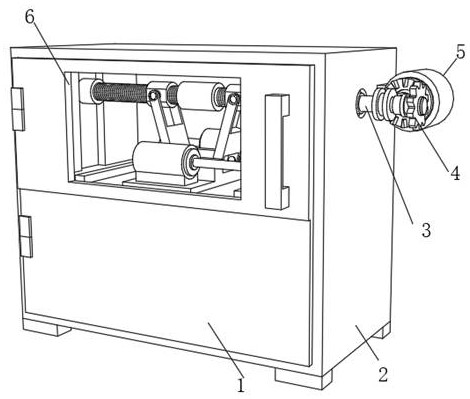
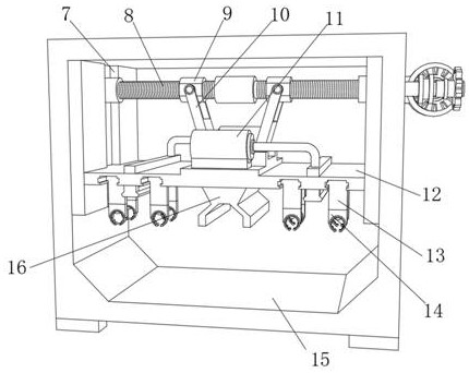
[0033] A high-efficiency electronic rotor impregnation device, such as Figure 1-4 As shown, it includes a main body box 2, the front side outer wall of the main body box 2 is hinged with a box door 1, and the top front outer wall of the main body box 2 is provided with a glass observation window 6, and the side outer wall of the main body box 2 is passed through a support. The plate is fixed with a motor 5, and the output end of the motor 5 is sleeved with a main gear, and the peripheral teeth of the main gear are meshed with a secondary gear 4, and the peripheral inner wall of the secondary gear 4 is inserted with a rotating shaft 3, and the end of the rotating shaft 3 is provided with Lifting mechanism, the inner walls of both sides of the main body box 2 are respectively fixed with guide plates by bolts, and the opposite side outer walls of each guide plate are provided with chute 7, the bottom end of the lifting mechanism is fixed with a sliding plate 12 by bolts, and the ...

Embodiment 2

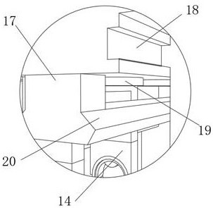
[0039] A high-efficiency electronic rotor impregnation device, such as Figure 5 As shown, in order to effectively promote the guidance of the wind; this embodiment makes the following improvements on the basis of Embodiment 1: each of the top outer walls of the air guide ring 19 is threaded with an air nozzle 27, and the air guide ring 19 is close to the air nozzle There is an air outlet 24 below 27, and the inner walls on both sides of the air outlet 24 near the bottom of the air nozzle 27 are connected with fixed shafts 26 by threads respectively, and the circumferential outer wall of the fixed shaft 26 is sleeved with an air guide sphere 25, and the bottom inner wall of the air outlet 24 The structure is an outwardly inclined structure; when the gas enters the air outlet 24 through the air nozzle 27, it effectively drives the rotation of the air guide sphere 25, so that the air outlet 24 is filled with gas, and the inner wall of the bottom inner ring of the air outlet 24 is...


PUM


Abstract

The invention discloses an electronic rotor paint dipping device with relatively high efficiency, and relates to the technical field of electronic rotor paint dipping. The invention aims to achieve the purpose of efficient paint dipping of the rotor. The electronic rotor paint dipping device specifically comprises a main body box, wherein a box door is hinged to the outer wall of one side of the front face of the main body box through a hinge, and a glass observation window is arranged in the outer wall of the front face of the top of the main body box; a motor is fixed to the outer wall of one side of the main body box through a supporting plate; the output end of the motor is sleeved with a main gear, and circumferential teeth of the main gear are meshed with a secondary gear; a rotating shaft is inserted into the circumferential inner wall of the secondary gear, and a lifting mechanism is arranged at the end of the rotating shaft; guide plates are fixed to the inner walls of the two sides of the main body box through bolts, and sliding grooves are formed in the outer walls of the opposite sides of the guide plates; a sliding plate is fixed to the bottom end of the lifting mechanism through bolts; and the two ends of the sliding plate are in sliding fit with the two sliding grooves. According to the electronic rotor paint dipping device, the defect of paint dipping of a single rotor is overcome, the rotor paint dipping efficiency is improved, and the production quantity of rotor paint dipping is also ensured.

Description

technical field [0001] The invention relates to the technical field of dipping paint for electronic rotors, in particular to a high-efficiency dipping paint device for electronic rotors. Background technique [0002] Rotor refers to the rotating body supported by bearings, mostly the main rotating parts in power machinery and working machinery. Objects such as optical discs that do not have their own axis of rotation can be considered a rotor when rigidly connected or attached. When the rotor rotates at certain speeds, it will deform greatly and cause resonance. The speed at which resonance is caused is called the critical speed of the rotor. After the rotor is produced, it needs to be dipped in paint. The rotor dipped in paint can fill the gaps and air layers of its coils. After curing, it can form a continuous and flat paint film on the surface of the dipped paint windings and components, and make the windings bonded into a whole, improving Improve the coil insulation an...

Claims


Application Information

Patent Timeline
Patent Type & Authority Applications(China)
IPC IPC(8): B05C3/02B05C9/12B05C13/02B05D3/04H02K15/12
CPCB05C3/02B05C9/12B05C13/02B05D3/0406H02K15/12
Inventor 龚爽
Owner 龚爽
Why Eureka
Try Eureka