A plant cleaning system for plant shampoo processing
A cleaning system and shampoo technology, applied in the direction of using liquid cleaning methods, cleaning methods and utensils, chemical instruments and methods, etc., can solve the problems of mixing into plants and slow efficiency, and achieve multi-benefit and labor-saving effects
- Summary
- Abstract
- Description
- Claims
- Application Information
AI Technical Summary
Problems solved by technology
Method used
Image
Examples
specific Embodiment approach 1
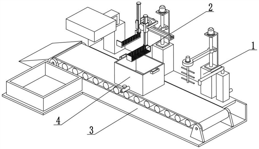
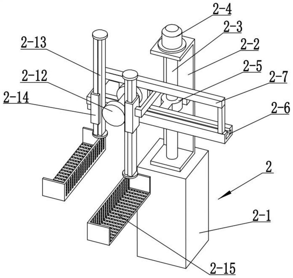
[0024] The following embodiment is illustrated in conjunction with the figure, the present invention relates to the field of shampoo processing technology, more specifically a plant shampoo processing plant cleaning system, comprising a churning cleaning mechanism 1, scum salvage mechanism 2, transport platform mechanism 3 and plant cleaning barrel 4, the agitation cleaning mechanism 1 is connected to the right end of the rear end of the transport platform mechanism 3, the scum salvage mechanism 2 is connected to the middle of the rear end of the transport platform mechanism 3, and the plant cleaning barrel 4 is located on the transport platform mechanism 3.
[0025] Plant cleaning bucket 4 is set up with multiple, the shampoo processing plants into a plurality of plant cleaning buckets 4, one by one placed on the transport platform mechanism 3, in each plant cleaning bucket 4 through the stirring cleaning mechanism 1 below, the stirring cleaning mechanism 1 will add water to the ...
specific Embodiment approach 2
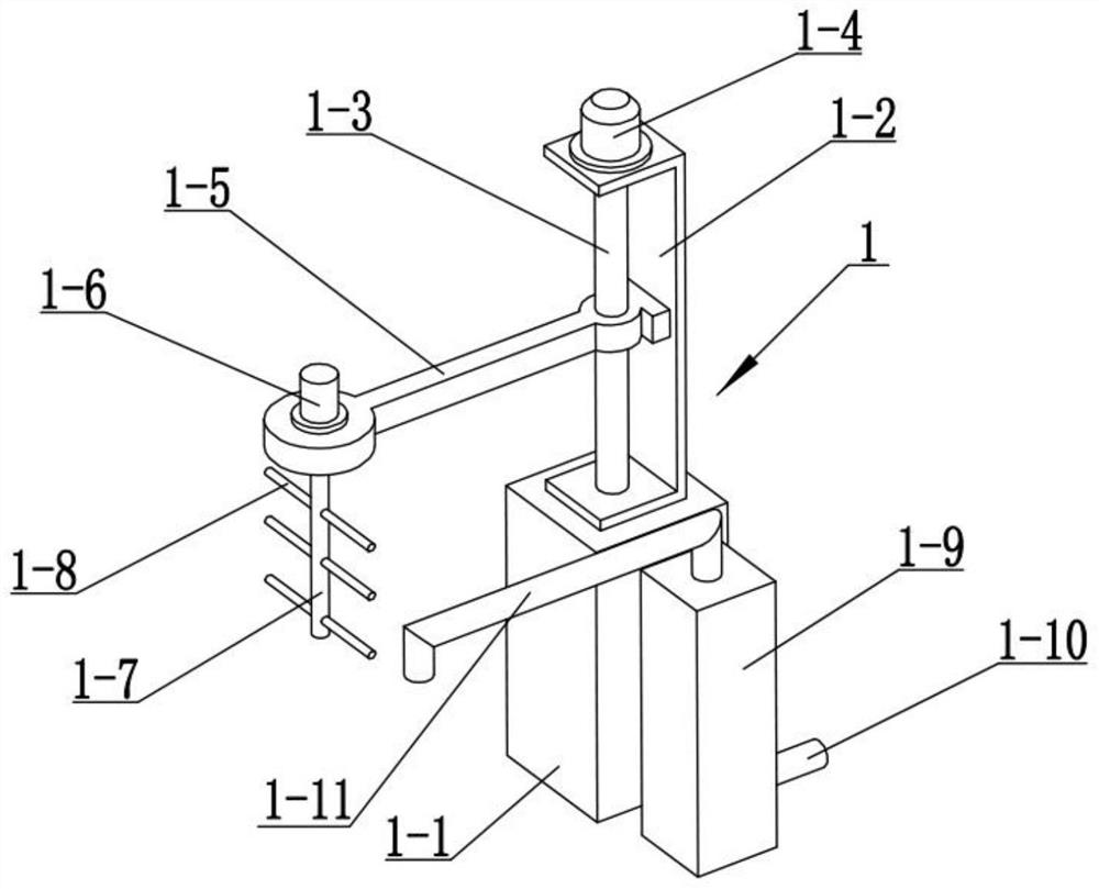
[0026]The following combined figure illustrates the present embodiment, the present embodiment of a further description of the embodiment, the agitation cleaning mechanism 1 comprises a height base 1-1, vertical slide 1-2, vertical screw 1-3, vertical motor 1-4, lifting beam 1-5, agitator motor 1-6, rotary shaft 1-7 and agitator rod 1-8, a plurality of agitators 1-8 are fixed on the rotating shaft 1-7, rotary shaft 1-7 top rotation connected to the bottom end of the front end of the lifting beam 1-5, The rotating shaft 1-7 is fixedly connected to the output shaft of the agitator motor 1-6, the agitator motor 1-6 is fixedly connected to the front end of the lifting beam 1-5, the rear end of the lifting beam 1-5 is connected by thread in the vertical screw 1-3, the vertical screw 1-3 rotation is connected to the vertical slide 1-2, the top of the vertical screw 1-3 is fixed to the output shaft of the vertical motor 1-4, the vertical motor 1-4 is fixed to the bottom end of the vertic...
specific Embodiment approach 3
[0028] The following combined figure illustrates the present embodiment, the present embodiment of the embodiment ii is further described, the rear end of the lifting beam 1-5 is a planar structure, the planar structure is used to cooperate with the rear end of the lifting beam 1-5 and the vertical slide 1-2 sliding contact; to avoid lifting beam 1-5 following the vertical lead screw 1-3 rotation.
PUM
 Abstract
Description
Claims
Application Information
 - R&D
- Intellectual Property
- Life Sciences
- Materials
- Tech Scout
- Unparalleled Data Quality
- Higher Quality Content
- 60% Fewer Hallucinations
Browse by: Latest US Patents, China's latest patents, Technical Efficacy Thesaurus, Application Domain, Technology Topic, Popular Technical Reports.
© 2025 PatSnap. All rights reserved.Legal|Privacy policy|Modern Slavery Act Transparency Statement|Sitemap|About US| Contact US: help@patsnap.com


