
Low-voltage large-current light-weight spot welding machine

A high-current, light-weight technology, applied in the direction of resistance welding equipment, electrode characteristics, welding equipment, etc., can solve the problems of increased cost, high price, heavy weight, etc., and achieve convenient production and maintenance, miniaturized welding gun structure, welding clamp compact effect

Pending Publication Date: 2021-05-07
HEFEI SANYU ELECTRIC
View PDF0 Cites 2 Cited by
  • Summary
  • Abstract
  • Description
  • Claims
  • Application Information

AI Technical Summary

Problems solved by technology

[0002] At present, lightweight and miniaturized resistance welding is more and more popular among the public, but most of the existing resistance welding tongs have complicated structural designs, and most of the welding power supply installation structures adopt complex frame installations, which are large in size and heavy in weight. To achieve the purpose of lightweight, the reason is that the assembly of welding tongs, driving device and welding power supply is complicated and mutually restricted. The modules cannot be maintained and replaced independently of each other, and the miniaturization design cannot be achieved. Therefore, users use large-volume resistance welding tongs. The purchase of expensive heavy-duty robotic equipment brings unpredictable safety hazards and increases costs. It is very important for the miniaturization design of the connection structures of the welding tongs

Method used


Image

  • Low-voltage large-current light-weight spot welding machine
  • Low-voltage large-current light-weight spot welding machine
  • Low-voltage large-current light-weight spot welding machine

Examples


Embodiment Construction

[0033] The embodiments of the present invention are described below through specific specific examples, and those skilled in the art can easily understand other advantages and effects of the present invention from the contents disclosed in this specification. The present invention can also be implemented or applied through other different specific embodiments, and various details in this specification can also be modified or changed based on different viewpoints and applications without departing from the spirit of the present invention.

[0034] It should be noted that the drawings provided in this embodiment are only to illustrate the basic concept of the present invention in a schematic way, so the drawings only show the components related to the present invention rather than the number, shape and the number of components in actual implementation. For dimension drawing, the type, quantity and proportion of each component can be changed at will in actual implementation, and t...


PUM


Abstract

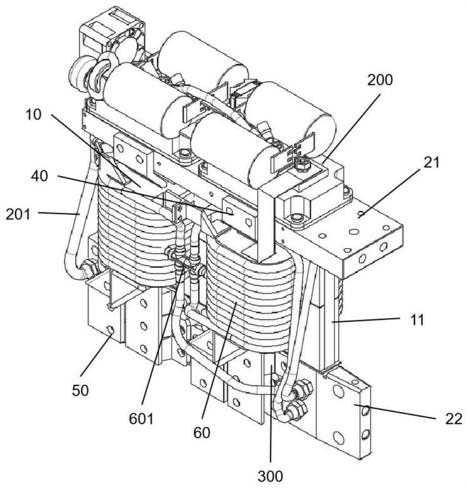
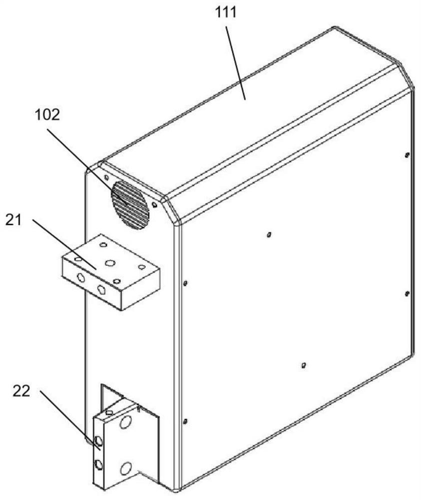
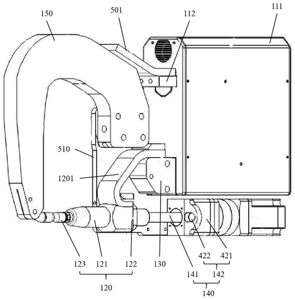
The invention provides a low-voltage large-current light-weight spot welding machine. The low-voltage large-current light-weight spot welding machine comprises a welding power source which comprises a box body, a first electrode and a second electrode, wherein the first electrode and the second electrode partially extend out of the box body; a movable arm structure which comprises a movable arm and a nut flange, wherein one end of the movable arm is connected with the nut flange; a connecting block which is arranged between a first conductive bridge and the first electrode; a driving device, wherein a driving rod of the driving device is connected with the nut flange and located at the bottom of the box body; and a stationary arm which is connected with the movable arm through a side connecting plate, wherein the side connecting plate is fixedly connected with the stationary arm and the connecting block through a plurality of fastening bolts, the side connecting plate is rotatably connected to the flange structure, and the movable arm structure, the connecting block, the driving device and the fixed arm are fixedly connected into an electrode holder stress connecting mechanism through the side connecting plate. The electrode holder stress connecting mechanism and the welding power source are mounted integrally. The movable arm structure and the stationary arm structure are compact, so that miniaturized design of an electrode holder is achieved, and the electrode holder and the welding power source are easy to disassemble, so that two electrode holders are switched rapidly.

Description

Technical field [0001] The invention belongs to the technical field of welding equipment, and specifically relates to a low-voltage, high-current lightweight spot welding machine. Background technique [0002] At present, lightweight and miniaturized resistance welding is becoming more and more popular among the public. However, most of the existing resistance welding clamps have complex structural designs. Most of the installation structures of the welding power sources adopt complex frame installations. They are large in size, heavy in weight, and cannot reach The reason for achieving lightweight is that the welding clamp, drive device and welding power source are assembled in a complex manner and restrict each other. Each module cannot be maintained and replaced independently of each other, making it impossible to achieve a miniaturized design. Therefore, users use large resistance welding clamps. The purchase of expensive heavy-duty robotic equipment brings unpredictable...

Claims


Application Information

Patent Timeline
IPC IPC(8): B23K11/11B23K11/31
CPCB23K11/115B23K11/31B23K11/314B23K11/315B23K11/311B23K11/3054
Inventor 袁忠杰
Owner HEFEI SANYU ELECTRIC
Learn More