Turning type rolling pin manufacturing device

A technology for manufacturing a device and a rolling pin, which is applied in the field of turning-type rolling pin manufacturing devices, which can solve problems such as low work efficiency, difficulty in controlling the strength and duration of scraping, and unsatisfactory rolling pin effect, so as to achieve good turning effect, reduce workload, The effect of improving work efficiency

Active Publication Date: 2021-05-07
泰安泰悦食坊食品有限公司
View PDF19 Cites 0 Cited by
  • Summary
  • Abstract
  • Description
  • Claims
  • Application Information

AI Technical Summary

Problems solved by technology

[0006] In order to overcome the current machine-made and hand-made rolling pins that require manually operated knives for scraping, because it is difficult to control the strength and duration of scraping manually, the effect of rolling pins is not ideal and the work efficiency is not high. The technical problem of the present invention To: Provide a turning rolling pin manufacturing device that can realize high-speed rotating logs, automatically and evenly scrape logs, and store the scraped debris in time

Method used


Image

  • Turning type rolling pin manufacturing device
  • Turning type rolling pin manufacturing device
  • Turning type rolling pin manufacturing device

Examples


Embodiment 1

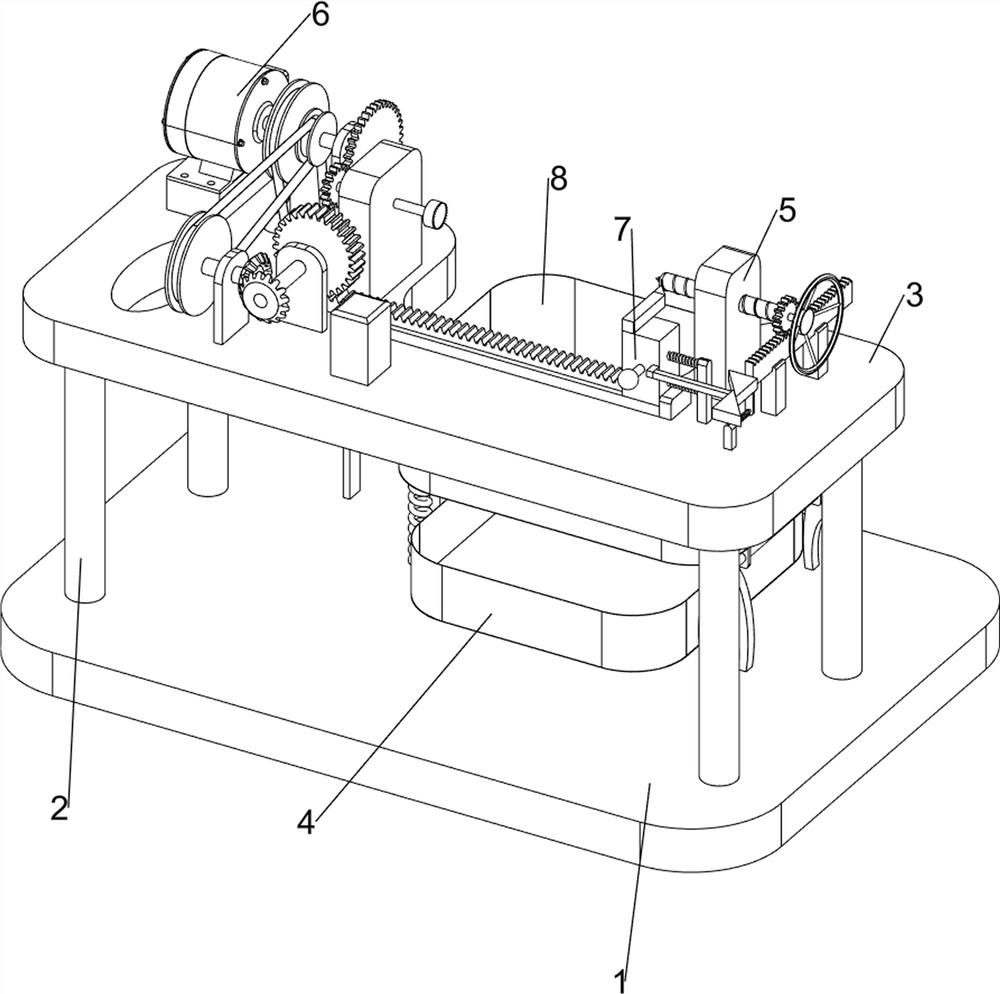
[0076] A turning type rolling pin making device, such as figure 1 As shown, it includes a base 1, a support column 2, a workbench 3, a collection frame 4, a clamping mechanism 5, a rotating mechanism 6 and a turning mechanism 7, and the left and right sides of the base 1 are symmetrically provided with a support column 2, and the support column 2 There is a working table 3 on the upper part, a collecting frame 4 is placed on the rear side of the top of the base 1, a rotating mechanism 6 is arranged on the working table 3, a clamping mechanism 5 is arranged on the working table 3 and the rotating mechanism 6, and the working table 3 and the rotating mechanism 6 is provided with turning mechanism 7.

[0077] When it is necessary to make a rolling pin, people first clamp a log with a certain length and uneven surface into the clamping mechanism 5, then turn the clamping mechanism 5 to clamp the log, and then start the rotating mechanism 6 to make the log rotate At the same time,...

Embodiment 2

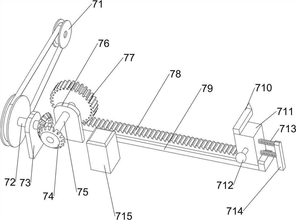
[0079] On the basis of Example 1, such as figure 2 , image 3 with Figure 4 As shown, the clamping mechanism 5 includes a first pillar 51, a handle 52, a one-way gear 53, a threaded rod 54, a thimble 55 and a pressing block 56, and the right side of the top of the workbench 3 is provided with a first pillar 51, and the first pillar 51 Top rotary type is provided with threaded rod 54, and threaded rod 54 right part is provided with handle 52 and one-way gear 53, and one-way gear 53 is connected with handle 52 rotationally, and threaded rod 54 left part is provided with thimble 55, and rotary mechanism 6 is provided with There is a pressing block 56 .

[0080] When clamping the log, first prepare a log whose length is about the same as the distance between the thimble 55 and the briquetting block 56, clamp the log between the thimble 55 and the briquetting block 56, and then turn the handle 52 clockwise to drive the screw thread Rod 54 rotates, and threaded rod 54 moves to ...

Embodiment 3

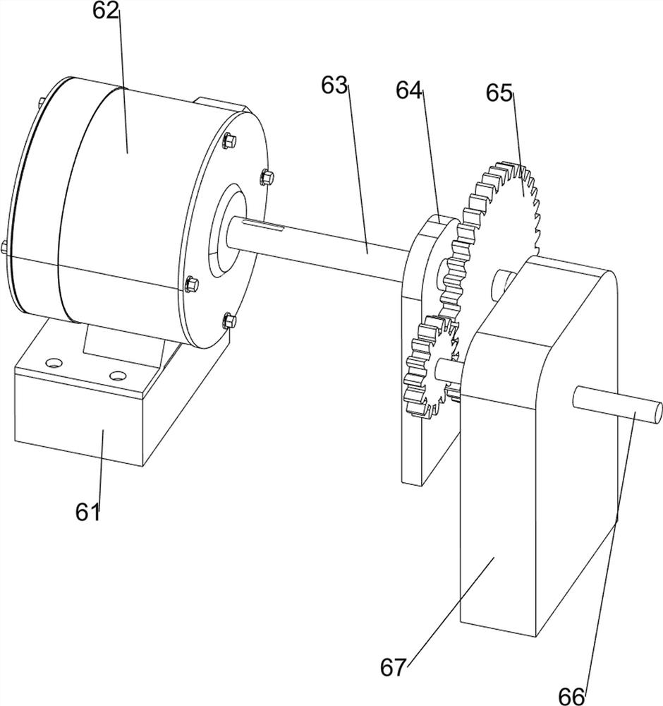
[0086] On the basis of Example 2, such as Figure 5 with Image 6 As shown, it also includes a filter mechanism 8 and a feeding mechanism 9 , the base 1 and the first rotating shaft 63 are provided with a filtering mechanism 8 , and the workbench 3 and the knife rest 711 are provided with a feeding mechanism 9 .

[0087] After turning, the tool rest 711 moves to the right to drive the blanking mechanism 9 to work, and then the log is released from between the thimble 55 and the pressing block 56, so that the log and debris fall into the filter mechanism 8 together, and at the same time the first The rotating shaft 63 rotates and drives the filter mechanism 8 to work, and then debris is screened into the collection frame 4 below, and the logs are left in the filter mechanism 8, and the logs are taken out afterwards, so that automatic feeding can be realized.

[0088] The filter mechanism 8 includes a seventh pillar 81, a fifth rotating shaft 82, a first connecting block 83, a ...


PUM


Abstract

The invention relates to a manufacturing device, in particular to a turning type rolling pin manufacturing device. According to the turning type rolling pin manufacturing device provided by the invention, high-speed rotation of logs can be realized, the logs can be automatically and uniformly scraped, and scraped chippings can be stored in time. The turning type rolling pin manufacturing device comprises four supporting columns, a workbench, a collecting frame and a rotating mechanism; the supporting columns are arranged on a base; the workbench is arranged at the upper parts of the supporting columns; the collecting frame used for collecting chippings is placed on the base; and the rotating mechanism is arranged on the workbench. According to the turning type rolling pin manufacturing device, through cooperation of a clamping mechanism, the rotating mechanism and a turning mechanism, the effects of high-speed rotation and automatic and uniform log scraping are achieved; and through cooperation of a filtering mechanism and a discharging mechanism, automatic discharging is achieved, and meanwhile the scraped chippings are filtered and stored in time.

Description

technical field [0001] The invention relates to a manufacturing device, in particular to a turning type rolling pin manufacturing device. Background technique [0002] A rolling pin is a wooden cooking tool with a cylindrical shape, used to twist and press dough until it is thinned. It is an indispensable tool for making noodles, dumpling wrappers, chaotic wrappers, etc. [0003] At present, there are two ways to make rolling pins: machine-made and hand-made. Machine-made is to clamp the log onto the wheel of the lathe. After starting the motor, hold the knife and slowly approach the high-speed rotating log. When the tool touches the log , move the knife slowly to cut off the excess part layer by layer, and turn off the motor when it reaches the appropriate thickness, while the manual production is to use the knife to scrape the log layer by layer until the appropriate thickness, and then remove the surface of the log The barbs are polished, and these two methods all need t...

Claims


Application Information

Patent Timeline
Patent Type & Authority Applications(China)
IPC IPC(8): B27C7/00B27C7/04B27M3/24
CPCB27C7/00B27C7/04B27M3/24
Inventor 万小华
Owner 泰安泰悦食坊食品有限公司
Why Eureka
Try Eureka