Slurry spraying device and method for manufacturing ceramic fiber filter tube

A technology of ceramic fiber and shotcrete, applied in household components, household appliances, other household appliances, etc., can solve the problem of affecting the uniformity and quality stability of ceramic fiber tubes, difficult to control the wall thickness and uniformity of the filter tube, and the degree of automation is not high. Advanced problems, to achieve the effect of reducing manual adjustment steps, improving quality, and improving the degree of automation

Active Publication Date: 2021-05-07
ZHEJIANG HAILIANG ENVIRONMENTAL MATERIALS +2
View PDF9 Cites 0 Cited by
  • Summary
  • Abstract
  • Description
  • Claims
  • Application Information

AI Technical Summary

Problems solved by technology

[0004] However, the automation degree of the existing ceramic fiber filter tube is not high. For example, the existing internal suction ceramic fiber filter tube needs to be grouted in batches, and the operation is complicated and it is difficult to control the wall thickness and uniformity of the filter tube.
Chinese patent CN105437366B discloses a suction filtration molding system for ceramic fiber tubes. The disclosed specific working process is as follows: inject the slurry mixed with ceramic fibers into the inner cavity of the tubular mold, and then vacuumize it. Molding is a separate and independent step, asynchronous operation, and one more cavity of material is added at a time. If the amount is not enough, it must be fed in multiple times, and the operation is complicated.
[0005] After the existing ceramic fiber filter tube is made, the flange section and the closed section need to be strengthened to improve the overall strength. Chinese patent CN107398133B discloses a method for strengthening the flange section and the closed section of the ceramic fiber filter tube. The best method is 1-4 times of soaking method, which affects the uniformity and quality stability of the ceramic fiber tube

Method used


Image

  • Slurry spraying device and method for manufacturing ceramic fiber filter tube

Examples


Embodiment Construction

[0033] The following will clearly and completely describe the technical solutions in the embodiments of the present invention with reference to the accompanying drawings in the embodiments of the present invention. Obviously, the described embodiments are only some, not all, embodiments of the present invention. The following description of at least one exemplary embodiment is merely illustrative in nature and in no way taken as limiting the invention, its application or uses. Based on the embodiments of the present invention, all other embodiments obtained by persons of ordinary skill in the art without creative efforts fall within the protection scope of the present invention.

[0034] Those skilled in the art can understand that, under the condition of no conflict, the features in the following embodiments and implementation manners can be combined with each other.

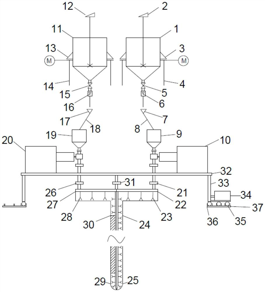
[0035] Such as figure 1 As shown, a spraying equipment for making ceramic fiber filter pipes is used for sp...


PUM

PropertyMeasurementUnit
diameteraaaaaaaaaa
lengthaaaaaaaaaa

Abstract

The invention discloses a slurry spraying device and method for manufacturing a ceramic fiber filter tube. The device comprises a rotating platform, a ceramic fiber slurry spraying module and a reinforcement slurry spraying module, wherein the ceramic fiber slurry spraying module and the reinforcement slurry spraying module rotate synchronously with the rotating platform; the ceramic fiber slurry spraying module comprises a ceramic fiber slurry feeding box, a ceramic fiber slurry metering pump, a ceramic fiber slurry spraying pipe and a ceramic fiber slurry liquid distributing plate; and the reinforcement slurry spraying module comprises a reinforcement slurry feeding box, a reinforcement slurry metering pump, a reinforcement slurry spraying pipe and a reinforcement slurry liquid distributing plate. According to the slurry spraying device and method, a plurality of spraying heads are arranged at proper positions of the whole ceramic fiber slurry / reinforcement slurry spraying pipe, and the liquid distributing plates are arranged corresponding to the spraying heads, so that the whole spraying pipes can spray slurry which is uniform up and down; and the spraying pipes rotate at a constant speed along with the rotating platform, so that the uniformity of the tube wall thickness of the whole formed ceramic fiber filter tube is ensured, and the quality of the ceramic fiber tube is improved.

Description

technical field [0001] The invention relates to the technical field of environmental protection, in particular to the production technology of a ceramic fiber filter tube for dust removal of high-temperature flue gas and purification of harmful substances. Background technique [0002] With the progress of society, people's awareness of environmental protection has been continuously strengthened, and the country's emission standards for waste gas have been further improved, especially the control of SO2, NOx, smoke and dioxin in waste gas has been strengthened, and the emission requirements of waste gas have reached ultra-clean standards. [0003] Ceramic fiber is a light-weight refractory fiber, its diameter is generally 2-5μm, and its length is mostly 30-250mm. Ceramic fiber filtration technology is one of the fastest-growing filtration technologies in recent years. The ceramic fiber filter tube is made of ceramic fiber with a certain thickness through a suitable special b...

Claims


Application Information

Patent Timeline
Patent Type & Authority Applications(China)
IPC IPC(8): B29C41/08B29C41/36B29C41/38B29C41/52B29C41/34B29C67/24B29L31/14
CPCB29C41/08B29C41/36B29C41/38B29C41/52B29C41/34B29C67/243B29L2031/14
Inventor 沈毅周友信陈勇刘雪松冯淼胡波王耀光李景慧周浩平俞奇开
Owner ZHEJIANG HAILIANG ENVIRONMENTAL MATERIALS
Why Eureka
Try Eureka