
Placement box for 3D printing equipment

A technology of 3D printing and placing boxes, which is applied in the directions of manufacturing auxiliary devices, dispersed particle filtration, processing platforms/substrates, etc., and can solve problems such as incapable of heat treatment

Pending Publication Date: 2021-05-07
东莞市宏鑫三维科技有限公司
View PDF4 Cites 0 Cited by
  • Summary
  • Abstract
  • Description
  • Claims
  • Application Information

AI Technical Summary

Problems solved by technology

[0004] The purpose of the present invention is to provide a storage box for 3D printing equipment to solve the problem that the heat accumulated at the bottom of the storage box cannot be processed in the above-mentioned background technology

Method used

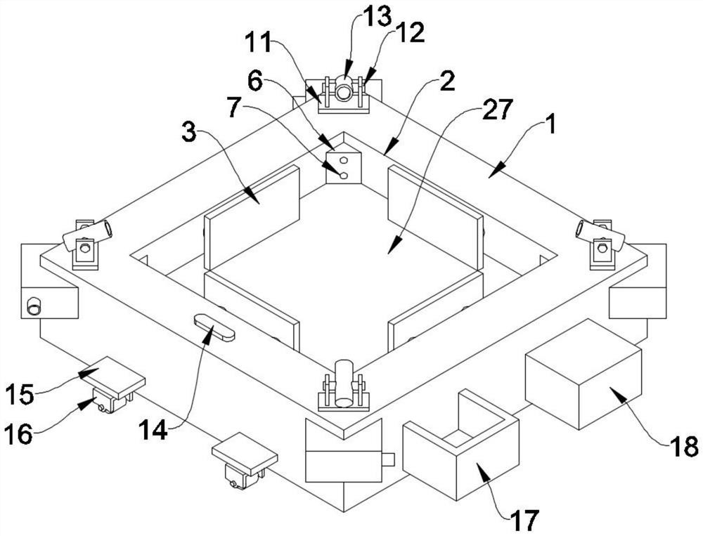
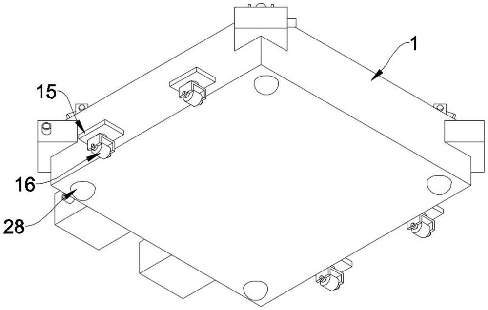
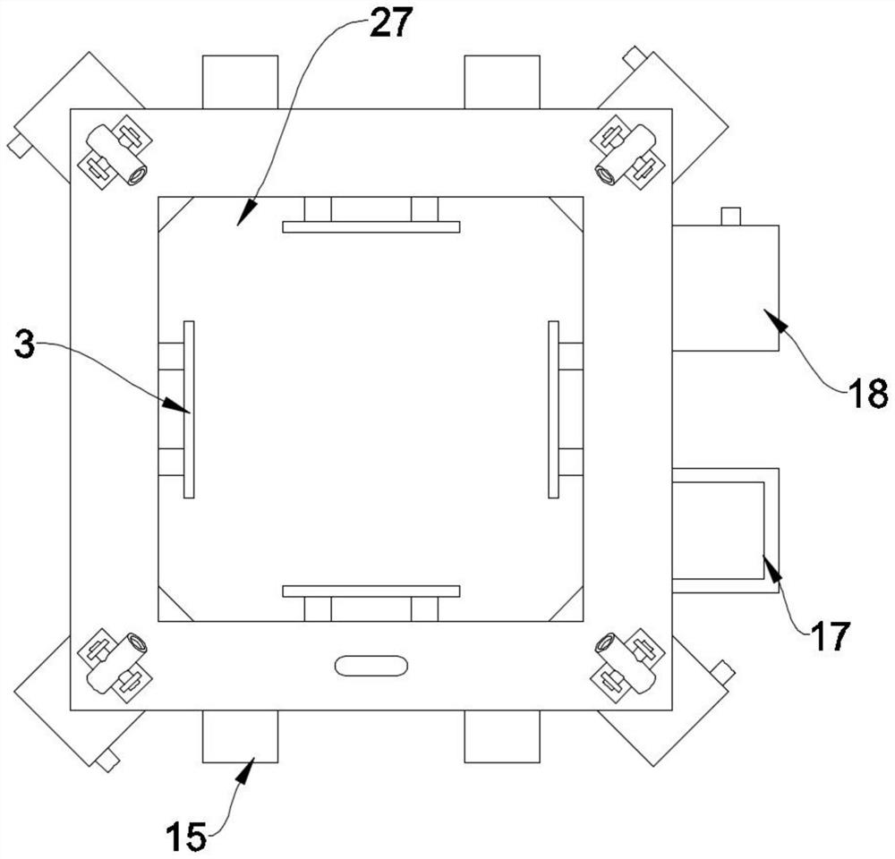

Image

  • Placement box for 3D printing equipment
  • Placement box for 3D printing equipment
  • Placement box for 3D printing equipment

Examples


Embodiment Construction

[0023] The following will clearly and completely describe the technical solutions in the embodiments of the present invention with reference to the accompanying drawings in the embodiments of the present invention. Obviously, the described embodiments are only some, not all, embodiments of the present invention.

[0024] see Figure 1-5 , an embodiment provided by the present invention: a storage box for 3D printing equipment, including a box base 1, a circulating cooling pipe 21 is arranged inside the box base 1, and a tee head 23 is arranged on the circulating cooling pipe 21, and the tee head 23 is fixedly connected with the circulating cooling pipe 21, and one side of the three-way head 23 is provided with a first electric valve 22, and the first electric valve 22 is fixedly connected with the circulating cooling pipe 21, and one side of the first electric valve 22 is provided with a lift pump 19 , the lifting pump 19 is fixedly connected with the circulating cooling pipe ...


PUM


Abstract

The invention discloses a placement box for 3D printing equipment, relates to the related field of 3D printing equipment, and aims to solve the problem that heat accumulated at the bottom of the placement box cannot be treated in the prior art. The placement box is characterized in that a circulating cooling pipe is arranged in a box base, a three-way head is arranged on the circulating cooling pipe, the three-way head is fixedly connected with the circulating cooling pipe, a first electric valve is arranged on one side of the three-way head and fixedly connected with the circulating cooling pipe, a lifting pump is arranged on one side of the first electric valve and fixedly connected with the circulating cooling pipe, and a second electric valve is arranged at the rear end of the three-way head; and a water return pipe is arranged at the rear end of the second electric valve and fixedly connected with the second electric valve, a recooling machine is arranged on the water return pipe and fixedly connected with the water return pipe, the recooling machine is fixedly connected with the circulating cooling pipe, and a water pumping pipe is arranged at the rear end of the recooling machine.

Description

technical field [0001] The invention relates to the related field of 3D printing equipment, in particular to a storage box for 3D printing equipment. Background technique [0002] 3D printing equipment, also known as a 3D printer, is a rapid prototyping process that produces a 3D model layer by layer. Its operation process is similar to that of a traditional printer, except that the traditional printer prints ink onto paper to form a 3D model. Two-dimensional planar drawings, while three-dimensional printers use liquid photosensitive resin materials, molten plastic filaments, gypsum powder and other materials to achieve layer-by-layer stacking and superimposition to form three-dimensional entities by spraying binders or extrusion, while 3D printing equipment When in use, a placement box is often used to fix it. [0003] However, when the existing 3D printing equipment is in use, a large amount of heat accumulation is often generated at the bottom of the equipment, which is ...

Claims


Application Information

Patent Timeline
IPC IPC(8): B29C64/245B29C64/20B29C64/30B33Y30/00B33Y40/00B01D46/10
CPCB29C64/245B29C64/20B29C64/30B33Y30/00B33Y40/00B01D46/10
Inventor 段北海
Owner 东莞市宏鑫三维科技有限公司
Learn More