
Gear chamber assembly and machining positioning device thereof

A technology of positioning device and gear chamber, which is applied in positioning device, metal processing equipment, metal processing mechanical parts, etc., can solve the problems of high processing cost, complicated clamping device design, and complicated connection structure of gear chamber assembly.

Active Publication Date: 2021-05-07
宁波裕隆汽车制泵有限公司
View PDF6 Cites 0 Cited by
  • Summary
  • Abstract
  • Description
  • Claims
  • Application Information

AI Technical Summary

Problems solved by technology

[0003] The existing gear chamber assembly has a complex connection structure and poor stability, and the gear chamber assembly structure is difficult to clamp during the machining process, resulting in complex design of the clamping device and high processing costs; and due to the instability of the clamping device, it will eventually As a result, the accuracy of assembly parts processing is reduced, and the product qualification rate is reduced

Method used


Image

  • Gear chamber assembly and machining positioning device thereof
  • Gear chamber assembly and machining positioning device thereof
  • Gear chamber assembly and machining positioning device thereof

Examples


Embodiment Construction

[0032] The present invention will be further described below in conjunction with the accompanying drawings and specific embodiments.

[0033] In the description of the present invention, it should be noted that the orientation or positional relationship indicated by the terms "bottom", "bottom", "upper end", "lower end" and "middle" are based on the orientation or positional relationship shown in the drawings , is only for the convenience of describing the present invention and simplifying the description, but does not indicate or imply that the referred device or element must have a specific orientation, be constructed and operated in a specific orientation, and thus should not be construed as limiting the present invention. In addition, it should be noted that the terms "first" and "second" are only used for descriptive purposes, and should not be understood as indicating or implying relative importance.

[0034] In the description of the present invention, it should be note...


PUM


Abstract

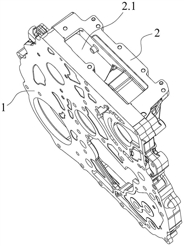
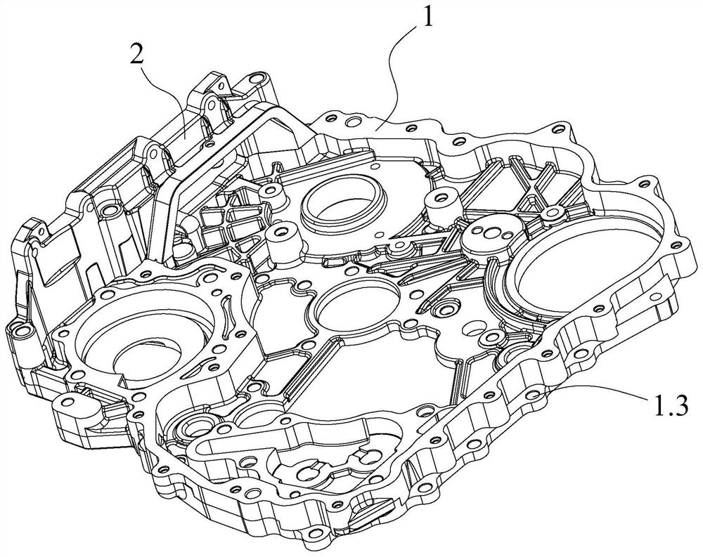
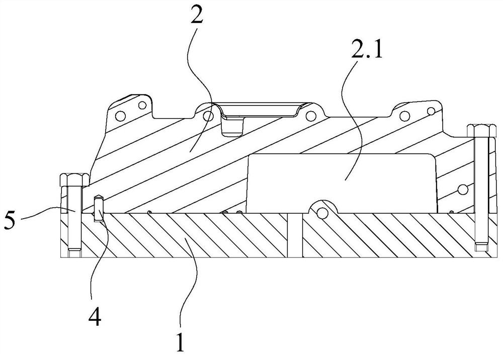
The invention discloses a gear chamber assembly. The gear chamber assembly comprises a gear chamber body and a chain wheel chamber frame, and a mounting part is arranged at one side of the gear chamber body; the chain wheel chamber frame is fixedly connected to the mounting part, and the chain wheel chamber frame and the mounting part are arranged at a vertical angle; a plurality of threaded holes and positioning holes are formed in the mounting part, and bolt through holes and positioning pins matched with positioning holes are correspondingly arranged on the mounting end surface of the chain wheel chamber frame; and first T-shaped grooves are formed in the side wall of the end, close to the mounting portion, of the chain wheel chamber frame, second T-shaped grooves are formed in the side face of one end of the gear chamber body, and when the chain wheel chamber frame and the gear chamber body are matched together, each first T-shaped grooves and the corresponding second T-shaped grooves are combined to form an I-shaped assembling groove, and an I-shaped positioning block is embedded in each I-shaped assembling groove. According to the gear chamber assembly and the machining positioning device thereof, the connecting structure is simple, the stability is high, the machining and clamping process is stable, the machining cost is low, and the precision of machined finished products is high.

Description

technical field [0001] The invention relates to the technical field of automobile engines, in particular to a gear chamber assembly and a processing and positioning device thereof. Background technique [0002] The gear chamber is an essential part of the engine mechanism and is mainly used to install gear components. In practical applications, there is usually a sprocket chamber on the gear chamber, and the sprocket chamber is fixedly connected with the gear chamber through the corresponding sprocket chamber frame. In actual production, the gear chamber and the sprocket are usually The chamber frame is designed as a gear chamber assembly structure for processing and production. [0003] The existing gear chamber assembly has a complex connection structure and poor stability, and the gear chamber assembly structure is difficult to clamp during the machining process, resulting in complex design of the clamping device and high processing costs; and due to the instability of t...

Claims


Application Information

Patent Timeline
IPC IPC(8): F02F7/00B23Q3/06
CPCF02F7/0095F02F7/0065F02F7/0021B23Q3/062
Inventor 胡松海励超剑
Owner 宁波裕隆汽车制泵有限公司
Learn More