
Gas supercharging device

A gas pressurization and two-stage pressurization technology, which is applied in the direction of liquid displacement machinery, piston pumps, multi-stage pumps, etc., can solve the problems of increasing piston area, reducing motor life, piston seal life, and increasing noise.

Pending Publication Date: 2021-05-07
河南斯贝克仪表科技有限公司
View PDF0 Cites 0 Cited by
  • Summary
  • Abstract
  • Description
  • Claims
  • Application Information

AI Technical Summary

Problems solved by technology

[0003] In the field of industrial metering and pressure calibration, the gas booster device is an important part of the automatic gas generating device. However, the gas generating device in the industry generally produces low gas pressure and low flow rate. If you need to output gas with high pressure and large flow rate , it is necessary to increase the area of ​​the piston, or increase the speed of the motor, the area of ​​the piston increases, the speed of the motor increases, and a motor with high power and high torque is also required, which wastes electric energy, the noise will also increase, and the volume of the gas generating device will also increase. , and the motor life and piston seal life will be reduced accordingly

Method used


Image

  • Gas supercharging device
  • Gas supercharging device
  • Gas supercharging device

Examples


Embodiment 1

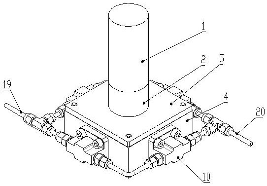
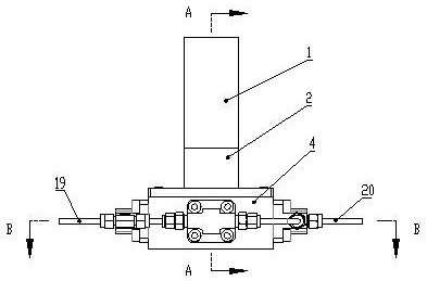
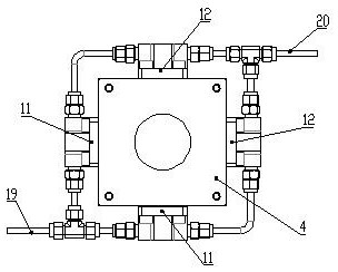
[0026] A gas supercharging device includes an air inlet 19, an output port 20, at least two stages of supercharging components, an eccentric component that provides reciprocating driving force for each level of supercharging component, and a drive mechanism that provides rotational motion for the eccentric component, each stage The booster assemblies are all provided with piston assemblies, and a single set of piston assemblies includes a cylinder 10 and a piston rod matched with the cylinder 10. The difference between different stages of booster assemblies is that the volume of the cavity of the cylinder 10 of the piston assembly is different. The pressure assembly is connected in series between the air inlet 19 and the output port 20 through the connecting air pipe, and the air path along the air inlet 19 to the output port 20 is recorded as a pressurized air path, Figure 5 The direction indicated by the middle arrow is the direction of gas flow. In the direction of the pres...

Embodiment 2

[0029] On the basis of Embodiment 1, a transmission case 4 is also included, the drive mechanism is installed on the transmission case 4, and the eccentric assembly is installed in the transmission case 4. The drive mechanism includes a motor 1 and a reducer 2, and the eccentric assembly It includes an eccentric shaft 6 and an eccentric top block arranged coaxially. The output shaft of the reducer 2 is connected to the eccentric shaft 6 through a flat key 3. The eccentric top block is installed on the outer ring of the eccentric shaft 6. The cylinder 10 is installed on the transmission On the side wall of the box body 4, one end of the piston rod extends into the cavity of the cylinder 10, and the other end of the piston rod abuts against the outer periphery of the eccentric top block, that is, the other end of the piston rod contacts the outer periphery of the eccentric top block. , its outer edge is always in contact with the other end of the piston rod and pushes the piston ...

Embodiment 3

[0032] On the basis of Embodiment 2, the lower part of the eccentric shaft 6 is rotationally connected with the transmission case 4 through the small bearing 8, the small bearing 8 is fixed on the bottom of the transmission case 4, and the eccentric top block adopts the large bearing 7 and is installed on the eccentric On the top of the shaft 6, the inner ring of the large bearing 7 is axially fixed by a circlip 9. The large bearing 7 is used to press the different piston rods sequentially. During the eccentric rotation process of the inner ring of the large bearing 7 with the eccentric shaft 6, the outer ring of the large bearing 7 presses the piston rods of different piston assemblies in turn, so that they face the cavity of the cylinder 10 The interior moves in a straight line. During the pressurization process, the outer ring of the large bearing 7 and the inner ring of the large bearing 7 will have a certain relative rotation, which can effectively avoid the vibration caus...


PUM


Abstract

The invention discloses a gas supercharging device which comprises a gas inlet, an output port, at least two stages of supercharging assemblies, an eccentric assembly for providing reciprocating driving force for each stage of supercharging assembly and a driving mechanism for providing rotary motion for the eccentric assembly, each stage of supercharging assembly is provided with a piston assembly, each piston assembly comprises an air cylinder and a piston rod matched with the air cylinder, the difference between the different stages of supercharging assemblies is that the volumes of air cylinder cavities of the piston assemblies are different, the different stages of supercharging assemblies are connected between the gas inlet and the output port in series through connecting gas pipes, a gas path between the gas inlet and the output port is marked as a supercharging gas path, and in the direction of the supercharging gas path, the volumes of the air cylinder cavities in the piston assemblies are sequentially reduced, and the eccentric assembly sequentially abuts against the piston rods of different piston assemblies in the rotating process. According to the gas supercharging device, the generated gas pressure can be increased under the condition that the volume of a gas generation device is not increased too much.

Description

technical field [0001] The invention relates to the technical field of calibration of pressure instruments, in particular to a gas booster device. Background technique [0002] In the measurement work of various industries, regular verification and maintenance of instruments and meters is required. During the verification and maintenance process, a high-pressure pressure source is an essential tool for regular inspection of instruments and meters. The gas booster device with gas medium is one of the commonly used types of high-pressure pressure sources. one. [0003] In the field of industrial metering and pressure calibration, the gas booster device is an important part of the automatic gas generating device. However, the gas generating device in the industry generally produces low gas pressure and low flow rate. If you need to output gas with high pressure and large flow rate , it is necessary to increase the area of ​​the piston, or increase the speed of the motor, the a...

Claims


Application Information

Patent Timeline
Patent Type & Authority Applications(China)
IPC IPC(8): F04B35/04F04B25/00F04B27/04F04B27/053F04B37/12
CPCF04B25/00F04B27/04F04B27/0404F04B27/053F04B27/0536F04B35/04F04B37/12
Inventor 韩利民都洪阳王于冲
Owner 河南斯贝克仪表科技有限公司
Learn More