
An improved fountain water pump drainage device

A drainage device and an improved technology, which are applied to pump devices, electromechanical devices, and components of pumping devices for elastic fluids, etc., can solve the problems of vibration of the submersible motor, the water suction port is exposed to the water surface, and the water body wastes energy. Easy to use, thorough drainage, reducing water absorption resistance and energy consumption

Active Publication Date: 2022-07-26
徐州飞龙机电制造有限公司
View PDF5 Cites 0 Cited by
  • Summary
  • Abstract
  • Description
  • Claims
  • Application Information

AI Technical Summary

Problems solved by technology

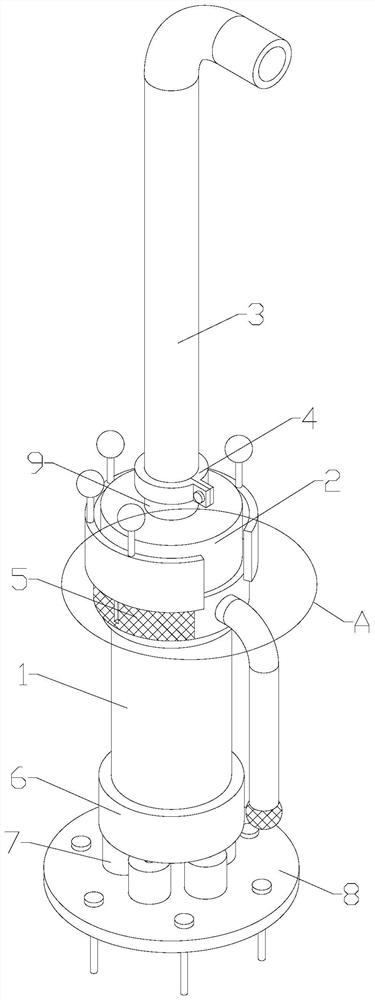
[0002] Fountain water pumps are often composed of water pumps, submersible motors and drainage pipes. The submersible motors and water pumps are connected and located below the water surface. The drainage pipes are connected to the outlet pipes of the water pumps and connected by flanges and bolts. Submerged below the water surface, and usually the submersible motor of the fountain water pump is located at the lower part of the pump body, the subsequent stage of drainage often causes the water suction port to be exposed to the water surface and cannot absorb water. It is also necessary to suck the water from the bottom of the water into the pump body through the suction pipe, which leads to a waste of energy in lifting the water body, and the submersible motor will vibrate when the fountain water pump is working, and the current drainage device cannot perform good shock absorption on it. Through the flange connection, disassembly and assembly are also relatively cumbersome, so we propose an improved fountain water pump drainage device to solve the above problems

Method used


Image

  • An improved fountain water pump drainage device
  • An improved fountain water pump drainage device
  • An improved fountain water pump drainage device

Examples


Embodiment Construction

[0022] The technical solutions in the embodiments of the present invention will be clearly and completely described below with reference to the accompanying drawings in the embodiments of the present invention. Obviously, the described embodiments are only a part of the embodiments of the present invention, but not all of the embodiments. Based on the embodiments of the present invention, all other embodiments obtained by those of ordinary skill in the art without creative efforts shall fall within the protection scope of the present invention.

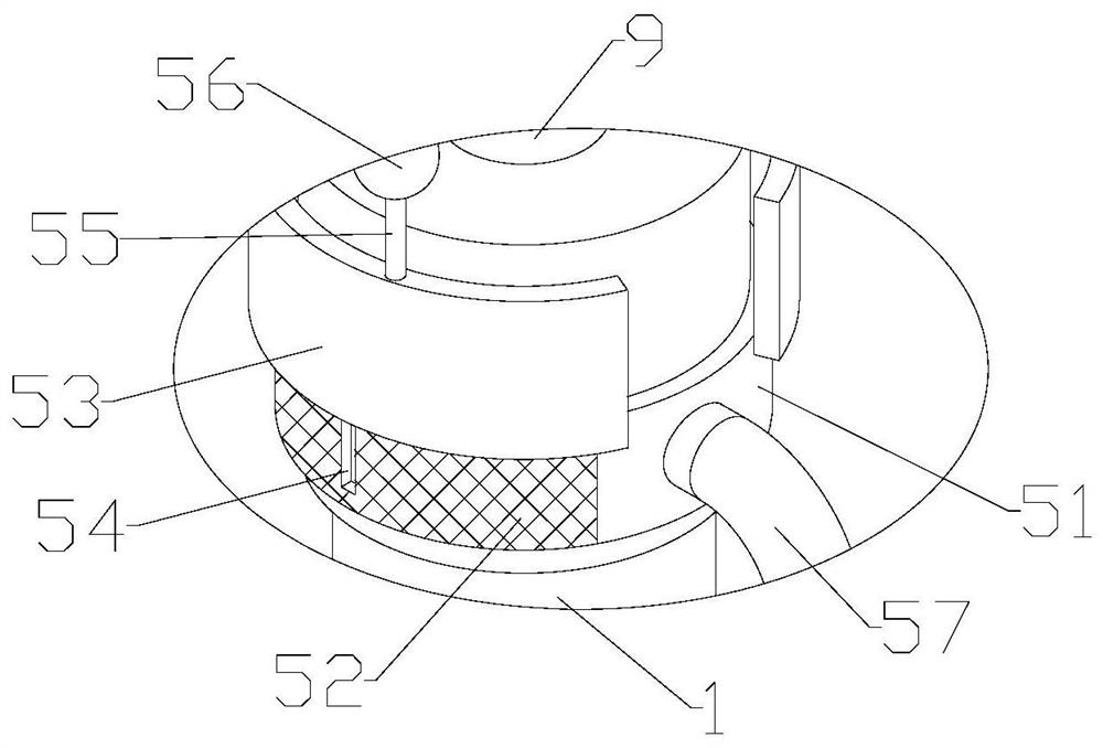
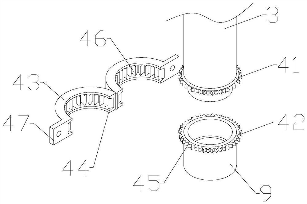
[0023] see Figure 1-5 , The present invention provides a technical solution: an improved fountain water pump drainage device, comprising a submersible motor 1, the top of the submersible motor 1 is fixedly connected to the pump body 2, the top of the pump body 2 is fixedly installed with a water outlet pipe 9, and the water outlet pipe 9 is connected to the drainage Pipe 3, the connection component 4 is installed between the drain pi...


PUM


Abstract

The invention discloses an improved fountain water pump drainage device, comprising a submersible motor, the top of the submersible motor is fixedly connected to a pump body, a water outlet pipe is fixedly installed on the top of the pump body, the water outlet pipe is connected to the drainage pipe, and a connection assembly is installed between the drainage pipe and the water outlet pipe , The outer wall of the pump body is provided with a water absorption component, the bottom of the submersible motor is secretly rotated through the bolts to the installation frame, the bottom of the installation frame is installed with a damping mechanism, the damping mechanism is connected to the base, and the base is connected to the bottom surface of the water bottom through anchor bolts. The damping mechanism is used for buffering between the installation frame and the base to reduce the vibration amplitude of the submersible motor and ensure the stability of the fountain pump. When the liquid level is higher than the pump body, it can directly absorb water from the pump body to reduce water absorption resistance and energy consumption. When the liquid level is lower than the pump body, it can absorb water from the bottom of the water to ensure thorough drainage.

Description

technical field [0001] The invention relates to the technical field of drainage devices, in particular to an improved fountain water pump drainage device. Background technique [0002] The fountain pump is often composed of a water pump, a submersible motor and a drain pipe. The submersible motor and the water pump are connected and located below the water surface. The drain pipe is connected to the water pump outlet pipe and connected by flanges and bolts. Submerged under the water surface, and the submersible motor of the fountain pump is usually located at the lower part of the pump body, the subsequent stage of drainage often causes the suction port to be exposed to the water surface and cannot absorb water. It is also necessary to suck the water at the bottom into the pump body through the suction pipe, which will lead to waste of energy in lifting the water body, and the submersible motor will vibrate when the fountain pump is working, and the current drainage device c...

Claims


Application Information

Patent Timeline
Patent Type & Authority Patents(China)
IPC IPC(8): F04D13/08F04D29/52F04D29/64H02K5/24
CPCF04D13/08F04D29/648F04D29/528H02K5/24
Inventor 张震
Owner 徐州飞龙机电制造有限公司
Learn More