Crack simulation calibration device based on fracture mechanics and optical fiber sensing

A technology of optical fiber sensing and fracture mechanics, which is applied in the direction of optical devices, measuring devices, and measurement of the change force of optical properties of materials when they are stressed. And other issues

Active Publication Date: 2021-05-07
HARBIN INST OF TECH
View PDF14 Cites 1 Cited by
  • Summary
  • Abstract
  • Description
  • Claims
  • Application Information

AI Technical Summary

Problems solved by technology

[0005] The present invention aims to solve the problem that the existing devices

Method used


Image

  • Crack simulation calibration device based on fracture mechanics and optical fiber sensing
  • Crack simulation calibration device based on fracture mechanics and optical fiber sensing
  • Crack simulation calibration device based on fracture mechanics and optical fiber sensing

Examples


specific Embodiment approach 1

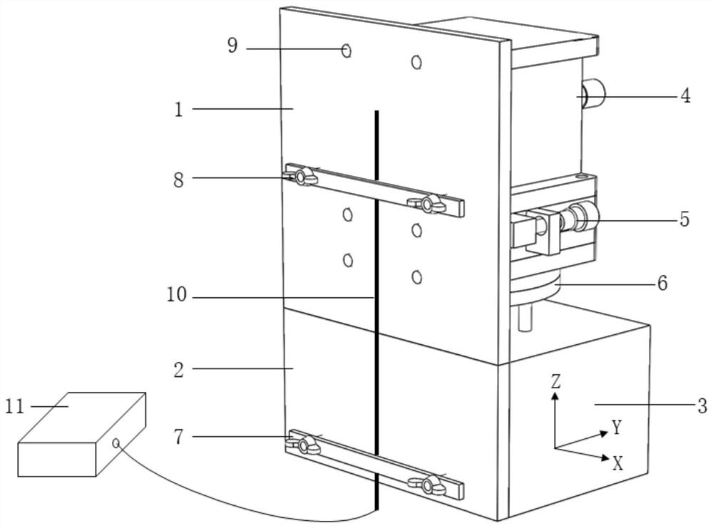
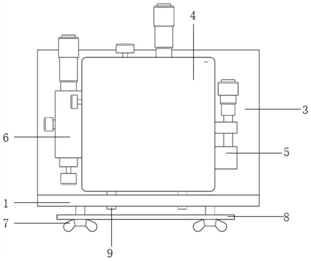
[0049] Specific implementation mode one: refer to Figure 1 to Figure 5 Describe this embodiment in detail, the crack simulation and calibration device based on fracture mechanics and optical fiber sensing described in this embodiment, the device includes an upper test board 1, a lower test board 2, a fixed support 3, a Z-direction slide table 4, Y-direction sliding table 5, R-direction sliding table 6, optical fiber sensor 10 and optical fiber sensing device 11;

[0050] The upper test plate 1 and the lower test plate 2 are overlapped along the vertical direction, and the lap joint between the upper test plate 1 and the lower test plate 2 is used to simulate cracks, and the fixed support 3 is fixed on one side of the lower test plate 2, and the R direction slides Table 6 is set on the fixed support 3, Y-direction slide table 5 is set on R-direction slide table 6, Z-direction slide table 4 is set on Y-direction slide table 5, Z-direction slide table 4 and the upper test plate ...

specific Embodiment approach 2

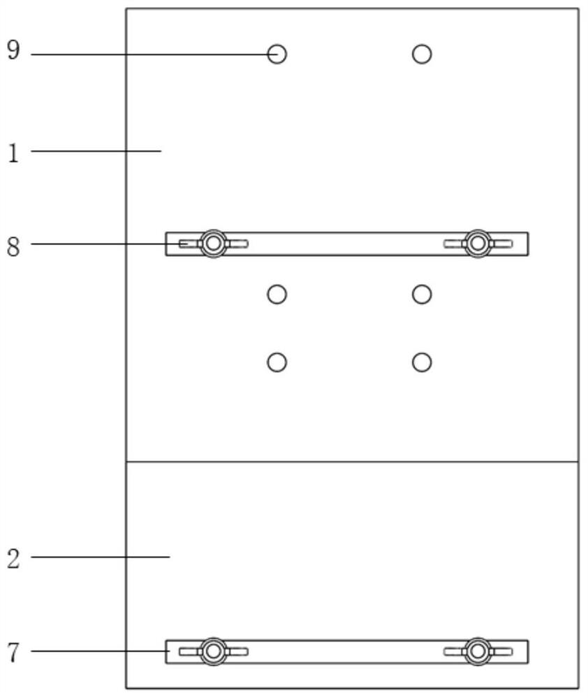
[0054] Specific embodiment 2: This embodiment is a further description of the crack simulation and calibration device based on fracture mechanics and optical fiber sensing described in specific embodiment 1. In this embodiment, the device also includes two sensor clamping plates 7

[0055] Two sensor clamping plates 7 fix the fixed fiber optic sensor 10 on the upper test board 1 and the lower test board 2 .

[0056] In this embodiment, the forms and openings of three basic cracks and their compound cracks in fracture mechanics can be simulated by adjusting the three-way combined slide table, and combined with the optical information obtained by the optical fiber sensor, the optical- Based on the force conversion relationship, a crack calibration method is proposed. The functions of the present invention can be specifically divided into crack simulation based on fracture mechanics and crack calibration based on optical sensing. Through the integrated design of the two functions...

specific Embodiment approach 3

[0059] Specific embodiment three: This embodiment is a further description of the crack simulation and calibration device based on fracture mechanics and optical fiber sensing described in specific embodiment two. In this embodiment, the device also includes a thumb screw 8,

[0060] The two sensor clamping plates 7 are fixed by thumb screws 8 .

[0061] In this embodiment, figure 2 The shown sensor clamping plate 7 and thumb screw 8 are used to fix the optical fiber sensor 10 itself or its data transmission armored wire, so as to ensure the deformation synchronization between the sensor and the upper test board 1 and the lower test board 2 . Three sets of limit screws 9 are respectively connected to the Z-direction slide 4, Y-direction 5, and R-direction slide 6 behind the upper test board 1, and the linkage between the upper test board 1 and the slide can be realized by adjusting the limit screws 9 , and then simulate the three basic cracks and their composite crack forms....


PUM


Abstract

The invention discloses a crack simulation calibration device based on fracture mechanics and optical fiber sensing, and relates to the field of engineering structure health monitoring. The invention aims to solve the problem that the stress of a crack cannot be detected due to lack of a device for simulating the crack of an engineering material in the prior art. An upper test plate and a lower test plate are in lap joint in the vertical direction, the lap joint position is used for simulating a crack, a fixed support is fixed to one side face of the lower test plate, an R-direction sliding table is arranged on the fixed support, a Y-direction sliding table is arranged on the R-direction sliding table, a Z-direction sliding table is arranged on the Y-direction sliding table, and the Z-direction sliding table is fixedly connected with one side face of the upper test plate; an optical fiber sensor is used for sensing the strain or wavelength change caused by the gap generated by the upper test plate and the lower test plate; and optical fiber sensing equipment is used for receiving and displaying strain or wavelength of the optical fiber sensor, and is also used for establishing displacement generated by at least one of the Z-direction sliding table, the Y-direction sliding table and the R-direction sliding table and a strain or wavelength change relationship corresponding to the displacement. The device is used for crack simulation and calibration.

Description

technical field [0001] The present invention relates to a crack simulation device. It belongs to the field of engineering structure health monitoring. Background technique [0002] Engineering materials will have defects and cracks in the process of production, processing and use. In fracture mechanics, cracks can be divided into three basic crack forms according to their force conditions. Among them, the opening type crack (Type I) is subjected to the tensile stress perpendicular to the crack surface, and the upper and lower surfaces of the crack are relatively open; the sliding type crack (Type II) is subjected to the shear stress parallel to the crack surface and perpendicular to the front edge of the crack. , the crack slides relatively in the plane; the tear-off type crack is also called plane shear type or anti-plane shear type crack (Type III), which is subjected to the shear stress parallel to the crack surface and the front edge of the crack. The upper and lower ...

Claims


Application Information

Patent Timeline
IPC IPC(8): G01B11/16G01L1/24G01L25/00G01N33/24
CPCG01B11/18G01B21/042G01L1/242G01L1/247G01L25/00G01N33/24
Inventor 马宪永张冀雯董泽蛟任前龙
Owner HARBIN INST OF TECH
Why Eureka
Try Eureka