Numerical reconstruction method for a residual stress field of a surface strengthening metal part

A residual stress and metal component technology, applied in the fields of electrical digital data processing, special data processing applications, instruments, etc., can solve the problems of difficulty in guaranteeing validity and complicated simulation process, so as to simplify the simulation and design process, and simplify the simulation process. , Economical effect

Active Publication Date: 2019-07-09
SOUTHWEST JIAOTONG UNIV
View PDF7 Cites 2 Cited by
  • Summary
  • Abstract
  • Description
  • Claims
  • Application Information

AI Technical Summary

Problems solved by technology

In actual engineering, the surface strengthening methods of components are different, such as shot peening, rolling, laser shock, surface induction hardening, etc. If the simulation is carried out according to the corresponding strengthening process, the simulation process will be very complicated and the effectiveness is difficult to guarantee

Method used


Image

  • Numerical reconstruction method for a residual stress field of a surface strengthening metal part
  • Numerical reconstruction method for a residual stress field of a surface strengthening metal part
  • Numerical reconstruction method for a residual stress field of a surface strengthening metal part

Examples


Embodiment 1

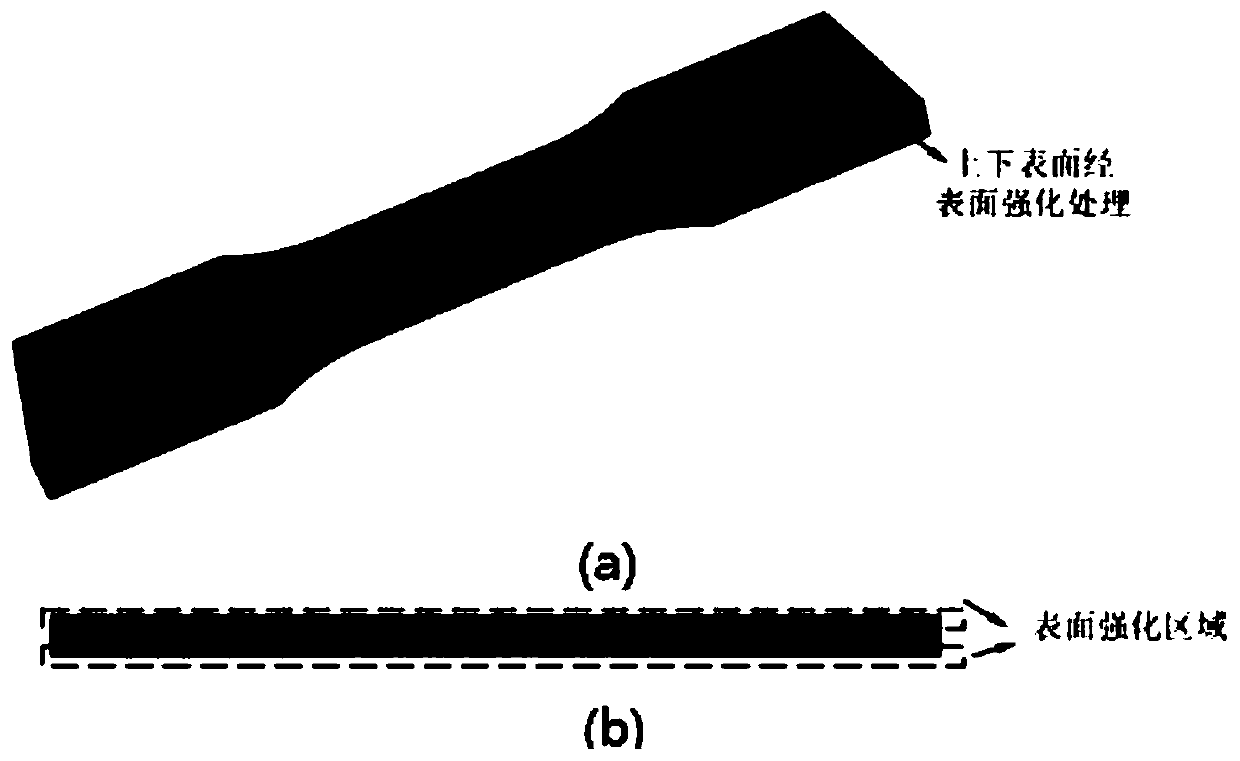
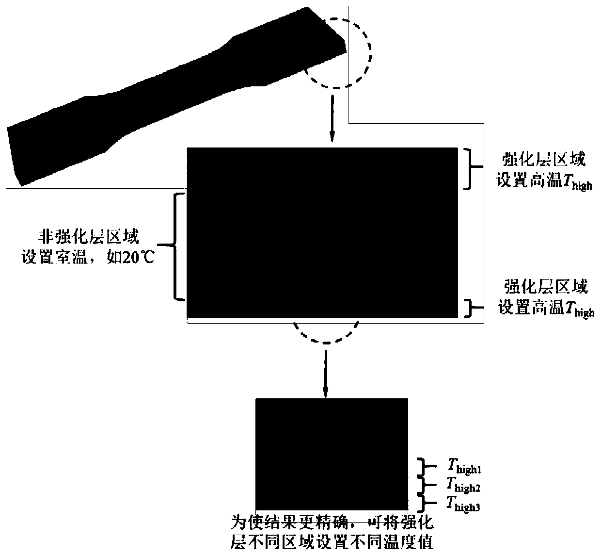
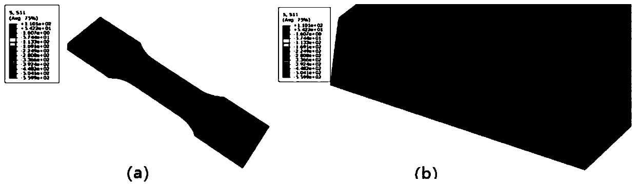
[0031] Embodiment 1: Its shape of a plate sample is as figure 1 As shown, the upper and lower surfaces of the sample have undergone surface strengthening treatment, and the mesh division in the strengthening layer area is relatively fine when dividing the mesh. Import the grid model into the finite element analysis software, set different temperature values ​​in the strengthened layer and non-strengthened layer of the sample, and use the temperature difference to generate compressive stress in the strengthened layer area. In order to make the result more accurate, a temperature gradient can be set in different areas of the strengthening layer, such as figure 2 shown. image 3 The residual compressive stress gradient distribution for the finite element simulation. When setting the temperature, it is necessary to conduct a trial calculation based on the experimental test value to find the appropriate temperature. T high , and finally obtain the simulated residual stress fie...

Embodiment 2

[0032] Embodiment 2: The specific steps are the same as in Example 1, except that the plate-shaped sample is changed into a cylindrical sample, and the outer surface of the cylindrical sample is a surface strengthening layer. This example demonstrates that the method described in the invention is not limited by the shape of the part.

Embodiment 3

[0033] Embodiment 3: It is a T-shaped welded joint, and its weld seam strengthening area is as follows Figure 8 shown. Under the action of fatigue load, the welded structure often initiates fatigue cracks at the weld to cause component fracture and failure. Therefore, strengthening treatment will be carried out at the weld to improve its fatigue performance in engineering. Figure 9 As shown, the temperature difference can be set between the weld area and other parts of the component to simulate the residual compressive stress after the weld area is strengthened. The method shown in the invention is also applicable to more complex structures such as welded structures.


PUM


Abstract

The invention discloses a numerical reconstruction method for a residual stress field of a surface strengthening metal part. Based on commercial CAE-based software, compression stress is generated inthe reinforced layer region by using the temperature difference. Different temperature values are set for a material or a component strengthening layer and other areas respectively, so that residual compressive stress fields generated by different surface strengthening processes are simulated. Adjustment is carried out according to actually-measured component residual stress data.The residual compressive stress fields are matched with the residual stress gradient distribution of the actually-measured data and subsequent numerical simulation calculation is facilitated. According to the method,a relatively accurate result can be obtained, the universality is high, the efficiency is high, the economical efficiency is good, the simulation and design process is greatly simplified, and a residual compressive stress field conforming to actual measurement data can be rapidly and economically deduced in engineering application.

Description

technical field [0001] The invention relates to the technical field of surface strengthening of mechanical parts, in particular to a numerical reconstruction method of a residual stress field of a surface strengthening metal part. Background technique [0002] Surface strengthening can effectively improve the surface properties of mechanical parts and components, and improve fatigue strength and wear resistance. The surface of the part under load is usually in the state of maximum stress and operates in different media environments. Therefore, the fatigue failure and damage of mechanical parts also mostly occur on the surface or start from the surface. Surface strengthening can introduce a certain residual compressive stress on the surface of the part, inhibit the initiation and expansion of fatigue cracks, thereby effectively improving the fatigue cracking resistance of the part and greatly extending the working life. However, the existence of surface residual compressive...

Claims


Application Information

Patent Timeline
Patent Type & Authority Applications(China)
IPC IPC(8): G06F17/50
CPCG06F30/23G06F2119/06
Inventor 吴圣川刘宇轩康国政阚前华
Owner SOUTHWEST JIAOTONG UNIV
Why Eureka
Try Eureka