Electronic transformer coil winding and stripping device

A technology of electronic transformers and winding devices, which is applied in the manufacture of coils, etc., can solve problems such as damage to coils, coil bumps, etc., and achieve the effects of easy arrangement, avoiding damage to the skeleton, and simple structure

Inactive Publication Date: 2021-05-07
全椒县丰顺和电子有限公司
View PDF0 Cites 5 Cited by
  • Summary
  • Abstract
  • Description
  • Claims
  • Application Information

AI Technical Summary

Problems solved by technology

[0004] What the present invention aims to overcome is the problem that the existing electronic transformer coil winding device is easy to cause the coil to be knocked when the coil is stripped off, which will further damage the coil. The purpose is to provide an electronic transformer coil coil stripping device

Method used


Image

  • Electronic transformer coil winding and stripping device
  • Electronic transformer coil winding and stripping device
  • Electronic transformer coil winding and stripping device

Examples


Embodiment 1

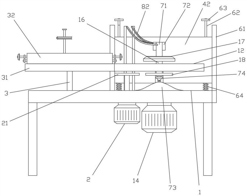
[0029] like Figure 1-7 Shown; A kind of electronic transformer coil winding stripping device, comprises:

[0030] Coil base 1, a turntable 12 and a wire reel seat 13 are installed on the coil base 1, the turntable 12 is driven by a stepper motor 14, and the stepper motor 14 is installed on the bottom of the coil base 1, and the turntable 12 is symmetrically installed with Two one-way bearing seats 15, two one-way bearing seats 15 are symmetrical about the axis of the turntable 12, each one-way bearing seat 15 is independently installed with a coil material shaft 16, and the upper end of the coil material shaft 16 is fixed with a material table 17, and the coil material shaft 16 lower end is fixed with driven gear 18;

[0031] Drive motor 2, the drive motor 2 is fixed on the lower part of the coil base 1, the output end of the drive motor 2 is fixed with a drive gear 21, the drive gear 21 is located between the turntable 12 and the coil base 1, and the driven gear 18 revolves...

Embodiment 2

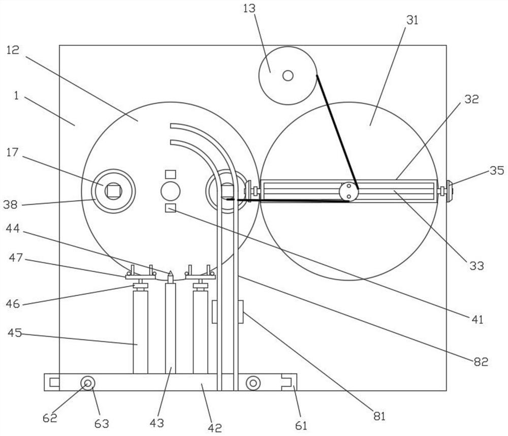
[0040] On the basis of Example 1, such as Figure 1-5 As shown; the material distribution shaft 3 is rotated on the coil base 1, and the distribution shaft 3 is fixed with a steering gear 31. A guide channel 32 is installed on it;

[0041] A first support screw 33 and a second support screw 34 are installed in the guide channel 32 for rotation, a first transmission gear 35 is fixedly installed on the first support screw 33, a second transmission gear 36 is fixedly installed on the second support screw 34, The first transmission gear 35 meshes with the second transmission gear 36, the two ends of the first support screw 33 are respectively equipped with bevel gears 37, the outer ring of the table 17 has a bevel gear ring 38, and the bevel gear 37 at one end of the first support screw 33 is engaged The bevel ring 38, the first support screw 33 is equipped with a moving seat 39, the moving seat 39 is equipped with a reciprocating screw 310 and a guide rod 311, and one end of the...

Embodiment 3

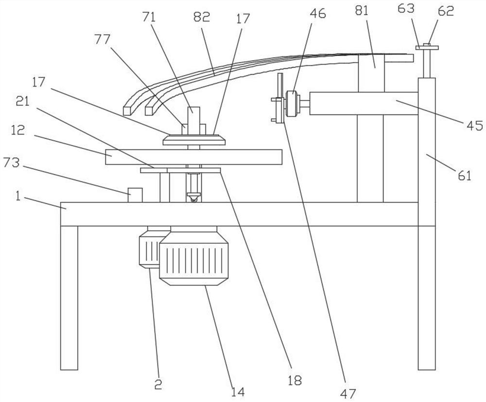
[0049] On the basis of Example 2, such as Figure 1-5 as well as Figure 8 As shown; the middle part of the turntable 12 is fixedly equipped with a knife seat 41, and the side of the coil base 1 is provided with a side plate 42, and a first electric push rod 43 is fixedly installed on the side plate 42, and the output end of the first electric push rod 43 faces the knife. Seat 41 is arranged, and the cutter 44 is fixed on the first electric push rod 43, and the second electric push rod 45 is respectively installed on the side plate 42 on both sides of the first electric push rod 43, and each second electric push rod 45 output end Steering motors 46 are installed respectively, the second electric push rod 45 is arranged one-to-one with the material table 17, the output end of the steering motor 46 is fixedly installed with a clamping plate 47, and the second electric push rod 45 is perpendicular to the clamping plate 47;

[0050] Two guide rails parallel to each other are arra...


PUM


Abstract

The invention discloses an electronic transformer coil winding and stripping device. A framework with a closed end moves along with rotation of a rotating disc, in the moving process, a buffer wheel at the lower end of a jacking and pressing column passes through a jacking and pressing block, the jacking and pressing block is enabled to jack the jacking and pressing column upwards, the jacking and pressing column drives a supporting rod and a material lifting block to move together, when the buffer wheel passes through the topmost end of the jacking and pressing block, the jacking and pressing column ascends to the maximum height, the jacking and pressing block jacks the framework to ascends to the upper part of the material lifting guide rail at the moment, when the punching wheel moves out of the jacking and pressing column, the jacking and pressing column descends, the framework on the material lifting block can be retained on the upper part of the material lifting guide rail, the upper end of the positioning column is separated from the material lifting guide rail along with the movement of the rotating disc and the gradual increase of the height of the material lifting guide rail, and the framework is completely stripped and detained on the material lifting guide rail, so that the stripping of the framework is achieved, the framework cannot be impacted in the whole process, the framework is prevented from being damaged, the stripped framework is arranged on the material lifting guide rail, and the framework is convenient to arrange.

Description

technical field [0001] The invention relates to the field of electronic transformer production equipment, in particular to an electronic transformer coil winding stripping device. Background technique [0002] An electronic transformer is an electronic device that converts the AC voltage of the mains into DC and then forms a high-frequency AC voltage output through semiconductor switching devices, electronic components and high-frequency transformer windings. It is also an electronic device described in electronics theory. An AC-DC-AC inverter circuit. In simple terms, it is mainly composed of a high-frequency transformer core (iron core) and two or more coils, which do not change their positions, and from one or more than two electrical circuits, through AC power by means of electric current. Magnetic induction is transformed into AC voltage and current. At the output end of the high-frequency transformer, high-frequency AC or DC power of different voltage levels is suppl...

Claims


Application Information

Patent Timeline
Patent Type & Authority Applications(China)
IPC IPC(8): H01F41/06
CPCH01F41/06
Inventor 张方伟张涛
Owner 全椒县丰顺和电子有限公司
Why Eureka
Try Eureka