Fuel cell and hydrogen supply system heating structure thereof

A fuel cell and heating structure technology, applied in the direction of fuel cell heat exchange, fuel cell, fuel cell additives, etc., can solve the problems of increasing power consumption of auxiliary systems, increasing component costs, and low efficiency of heating methods

Inactive Publication Date: 2021-05-07
SHANGHAI HYDROGEN PROPULSION TECH CO LTD
View PDF13 Cites 1 Cited by
  • Summary
  • Abstract
  • Description
  • Claims
  • Application Information

AI Technical Summary

Problems solved by technology

Due to the low temperature of the working fluid supplied from the hydrogen bottle, it is easy to condense and produce liquid water after mixing with the high-temperature and high-humidity ejection fluid, which will easily cause the stack to be flooded, resulting in poor consistency and reduced life of the stack, especially in low temperature environments , the effect is more prominent
[0003] There are currently two heating methods for fuel cell hydrogen supply: one is to add a heating resistance wire to the pressure reducer or the medium-pressure hydrogen supply pipe, and use electric energy to heat the hydrogen supply gas. On the one hand, this heating method will

Method used


Image

  • Fuel cell and hydrogen supply system heating structure thereof
  • Fuel cell and hydrogen supply system heating structure thereof
  • Fuel cell and hydrogen supply system heating structure thereof

Examples


Embodiment Construction

[0028] One of the cores of the present invention is to provide a fuel cell hydrogen supply system heating structure to achieve the purpose of improving the hydrogen supply heating method and eliminating the shortcomings of the existing two hydrogen supply heating methods.

[0029] Another core of the present invention is to provide a fuel cell based on the above fuel cell hydrogen supply system heating structure.

[0030] The following will clearly and completely describe the technical solutions in the embodiments of the present invention with reference to the accompanying drawings in the embodiments of the present invention. Obviously, the described embodiments are only some, not all, embodiments of the present invention. Based on the embodiments of the present invention, all other embodiments obtained by persons of ordinary skill in the art without making creative efforts belong to the protection scope of the present invention.

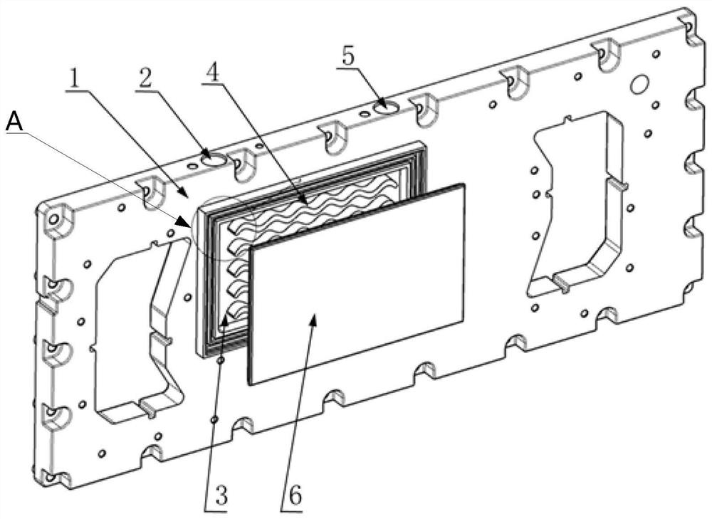
[0031] see figure 1 , figure 1 A schematic ...


PUM


Abstract

The invention relates to a fuel cell and a hydrogen supply system heating structure thereof. The hydrogen supply system heating structure of the fuel cell comprises a galvanic pile metal end plate; the galvanic pile metal end plate is provided with a heat exchange flow channel; and the heat exchange flow channel is provided with an inlet and an outlet on the surface of the galvanic pile metal end plate. The heat exchange flow channel is arranged on the galvanic pile metal end plate, so that hydrogen supply gas flows through the heat exchange flow channel to exchange heat with the galvanic pile metal end plate, so that the hydrogen supply gas can be heated by utilizing the waste heat of a galvanic pile, and heating equipment such as a heating resistance wire does not need to be added, and therefore, the safety of hydrogen supply is ensured while the cost and the power consumption are reduced; the galvanic pile metal end plate is made of metal, is generally made of aluminum alloy and has good thermal conductivity. Compared with a cooling liquid pipeline heat exchange mode, the above heat exchange mode has higher heat exchange efficiency and avoids the increase of flow resistance of a cooling liquid pipeline; in conclusion, the heat exchange structure of the heating structure of the invention has the advantages of simplicity, easiness in implementation, good heat exchange effect, high heat exchange speed, and high reliability, and is particularly suitable for a fuel cell anode circulating system using an ejector.

Description

technical field [0001] The invention relates to the technical field of fuel cells, in particular to a fuel cell and a heating structure for a hydrogen supply system thereof. Background technique [0002] In the fuel cell system, the working fluid of the injector is the hydrogen decompressed from the high-pressure hydrogen bottle, and the injector fluid is the high-temperature and high-humidity mixed gas at the anode outlet of the stack. Due to the low temperature of the working fluid supplied from the hydrogen bottle, it is easy to condense and produce liquid water after mixing with the high-temperature and high-humidity ejection fluid, which will easily cause the stack to be flooded, resulting in poor consistency and reduced life of the stack, especially in low temperature environments , the impact is more pronounced. [0003] There are currently two heating methods for fuel cell hydrogen supply: one is to add a heating resistance wire to the pressure reducer or the medium...

Claims


Application Information

Patent Timeline
IPC IPC(8): H01M8/0206H01M8/0258H01M8/0267H01M8/04007
CPCH01M8/0206H01M8/0258H01M8/0267H01M8/04074Y02E60/50
Inventor 黄争王鸿鹄尚鹏飞齐同仑
Owner SHANGHAI HYDROGEN PROPULSION TECH CO LTD
Why Eureka
Try Eureka