Measurement device
A measuring device and measuring unit technology, which is applied in the direction of measuring device, diagnostic recording/measurement, testing moving fluid/granular solid, etc., can solve problems such as inability to output measurement signals, and achieve the effect of improving convenience
- Summary
- Abstract
- Description
- Claims
- Application Information
AI Technical Summary
Problems solved by technology
Method used
Image
Examples
no. 1 approach
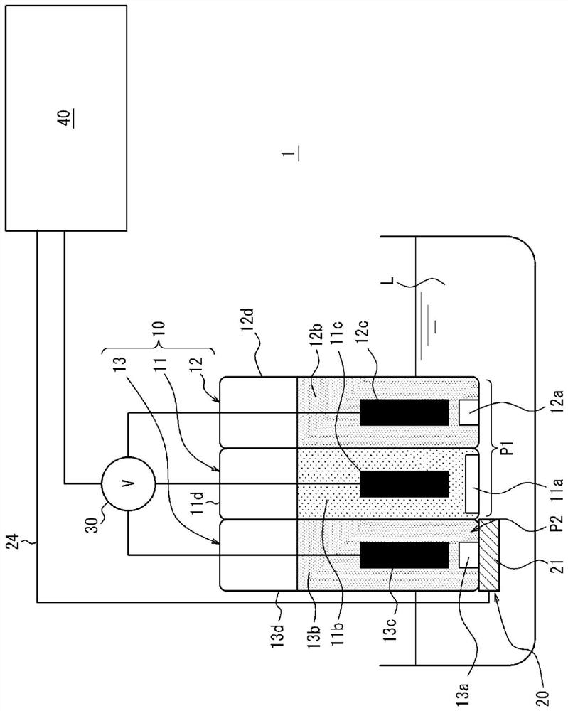
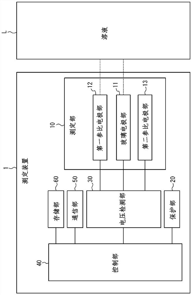
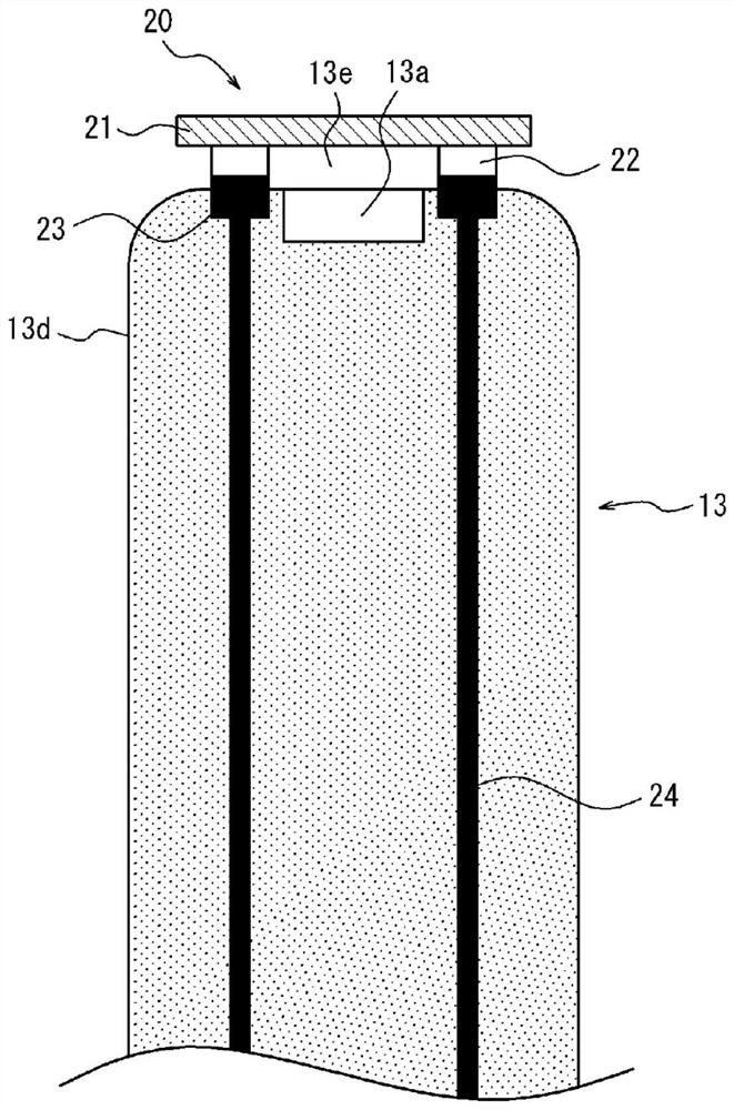
[0031] refer to Figure 1 to Figure 8 The configuration and functions of the measurement device 1 according to the first embodiment will be mainly described.
[0032] figure 1 It is a schematic diagram showing an example of the configuration of the measurement device 1 according to the first embodiment. The measurement device 1 of the first embodiment acquires information on the state of the solution L. FIG. In the first embodiment, the "information about the state of the solution L" includes the pH concentration, that is, the hydrogen ion concentration. The measurement device 1 of the first embodiment has a plurality of electrode units for glass electrode type pH measurement. if refer to figure 1 , the measurement device 1 has a measurement unit 10 and a protection unit 20 mounted on the measurement unit 10 .
[0033] The measurement unit 10 outputs a measurement signal related to the state of the solution L. The measurement unit 10 has: a first part P1 in a usable stat...
no. 2 approach
[0083] Figure 9 It is a schematic diagram showing an example of the configuration of the measuring device 1 of the second embodiment. refer to Figure 9 The configuration and functions of the measurement device 1 according to the second embodiment will be mainly described.
[0084] In the first embodiment, it was described that the information on the state of the solution L includes the pH concentration, and the measurement unit 10 has each electrode unit for glass electrode type pH measurement, but the present invention is not limited thereto. In the measurement device 1 of the second embodiment, for example, the information on the state of the solution L may include ion concentration, and the measurement unit 10 includes a first ISFET 71 and a second ISFET 72 . The configuration other than the measurement unit 10 of the measurement device 1 of the second embodiment is the same as that of the first embodiment, and the above description of the first embodiment is directly a...
no. 3 approach
[0090] Figure 10 It is a schematic diagram showing an example of the configuration of the measuring device 1 of the third embodiment. refer to Figure 10 The configuration and functions of the measurement device 1 according to the third embodiment will be mainly described.
[0091] In the measurement device 1 of the third embodiment, for example, information related to the state of the solution L may include ion concentration or chemical component composition, and the measurement unit 10 has a first metal thin film 81, a second metal thin film 82, a prism substrate 83 and a photodetector not shown. The configuration other than the measurement unit 10 of the measurement device 1 of the third embodiment is the same as that of the first embodiment, and the above description of the first embodiment is directly applied to this configuration. The same components as in the first embodiment are denoted by the same reference numerals, and description thereof will be omitted. Diffe...
PUM
 Abstract
Description
Claims
Application Information
 - R&D
- Intellectual Property
- Life Sciences
- Materials
- Tech Scout
- Unparalleled Data Quality
- Higher Quality Content
- 60% Fewer Hallucinations
Browse by: Latest US Patents, China's latest patents, Technical Efficacy Thesaurus, Application Domain, Technology Topic, Popular Technical Reports.
© 2025 PatSnap. All rights reserved.Legal|Privacy policy|Modern Slavery Act Transparency Statement|Sitemap|About US| Contact US: help@patsnap.com


