Axial crusher

A pulverizer, axial technology, applied in the direction of grain processing, etc., can solve the problems of difficult control of material crushing effect, poor material crushing effect, large power consumption, etc., to increase the number of moving knife groups and fixed knives, and improve the crushing efficiency. effect, the effect of reducing power consumption

Pending Publication Date: 2021-05-11
HEGANG TIANFENG AGRI MACHINERY MFG
View PDF0 Cites 0 Cited by
  • Summary
  • Abstract
  • Description
  • Claims
  • Application Information

AI Technical Summary

Problems solved by technology

[0004] In order to solve the problems of low crushing efficiency, poor material crushing effect, large power consumption and difficult control of material crushing effect in the existing pulverizer, the present invention proposes an axial pulverizer

Method used


Image

  • Axial crusher

Examples


specific Embodiment approach 1

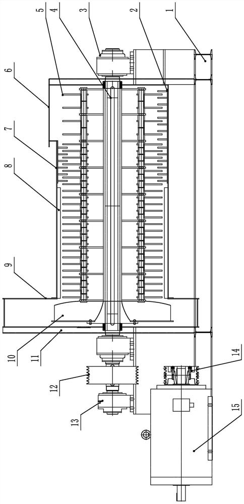
[0027] Embodiment 1: An axial pulverizer, comprising a base 1, a fixed knife set 2, a rotor bearing 3, a pulverizing rotor 4, a moving knife set 5, a housing 7, a rubbing plate 8, a fan casing 9 and fan blades 10,

[0028] The middle part of the upper surface of the base 1 is provided with a housing 7, and the middle part of one end surface of the housing 7 is provided with a through hole, the other end of the housing 7 is connected with the fan casing 9, and the two ends of the upper surface of the base 1 are provided with rotor bearings 3. The rotor 4 is arranged inside the housing 7 and the fan casing 9, and each end of the crushing rotor 4 is connected to a rotor bearing 3; the outside of the crushing rotor 4 is provided with multiple sets of moving knife sets 5 and fan blades 10; the fan blades 10 is set inside the fan casing 9; multiple sets of moving knife groups 5 are set inside the housing 7; one end of the housing 7 is surrounded by a plurality of fixed knife groups 2...

specific Embodiment approach 2

[0030] Specific embodiment two: described power unit comprises driven pulley 12, motor pulley 14 and motor 15; Wherein one end of crushing rotor 4 two ends passes through rotor bearing 3 and passes driven pulley 12; Described motor pulley 14 and The motor shaft of the motor 15 is connected, and the driven pulley 12 is connected with the motor pulley 14 by a belt.

[0031] Other implementation manners are the same as the specific implementation manner 1.

specific Embodiment approach 3

[0032] Specific embodiment three: one of the two ends of the pulverizing rotor 4 passes through the rotor bearing 3 and the motor pulley 14 and then passes through the supporting bearing 13;

[0033] The support bearing 13 is arranged on the upper surface of the base 1 .

[0034] Other implementation manners are the same as the second embodiment.


PUM


Abstract

The invention discloses an axial crusher, relates to the field of crushers, and aims to solve the problems that an existing crusher is low in crushing efficiency, poor in material crushing effect, large in power consumption and not easy to control in the material crushing effect. A shell is arranged in the middle of the upper surface of a base, and a through hole is formed in the middle of one end face of the shell; and the other end of the shell communicates with a fan shell, rotor bearings are arranged at the two ends of the upper surface of the base, a crushing rotor is arranged in the shell and the fan shell, and each end of the crushing rotor is connected with one rotor bearing. A plurality of movable cutter groups and fan blades are arranged outside the crushing rotor; the fan blades are arranged in the fan shell; the plurality of movable cutter groups are arranged in the shell; a plurality of fixed cutter groups are arranged at one end of the shell in a surrounding manner along the inner wall of the shell; a rubbing plate is arranged at the other end of the shell along the inner wall of the shell in a surrounding manner; a feeding hole is formed at the top of one end of the shell; and the crushing effect is improved, meanwhile, the screening effect is achieved, discharging is smoother and more uniform, and the production cost is reduced.

Description

technical field [0001] The invention relates to the field of pulverizers, in particular to an axial pulverizer. Background technique [0002] When the existing pulverizer works, the material moves tangentially along the pulverizer axis, the area of ​​the shell participating in the pulverization work is small, the pulverization efficiency is low, the pulverization effect of the material is not good, the power consumption is large, and the pulverization effect of the material is difficult to control, and it can only be controlled by Add sieves or change the size of the sieve holes, the materials are mixed together inside the pulverizer, and it is not easy to separate, resulting in waste of power. [0003] To sum up, the existing pulverizers have low crushing efficiency, poor material crushing effect, high power consumption, and difficult control of material crushing effect. Contents of the invention [0004] The present invention proposes an axial pulverizer to solve the pr...

Claims


Application Information

Patent Timeline
Patent Type & Authority Applications(China)
IPC IPC(8): B02C18/14B02C18/18B02C18/22B02C18/16B02C23/24
CPCB02C18/14B02C18/16B02C18/18B02C18/2216B02C23/24
Inventor 彭洪光
Owner HEGANG TIANFENG AGRI MACHINERY MFG
Why Eureka
Try Eureka