Floating clamp for honing connecting rod big end hole

A technology of connecting rod big end and floating fixture, which is used in honing machine tools, grinding drive devices, manufacturing tools, etc. Meet the requirements, the verticality error of the two ends of the big hole is large, etc., to meet the requirements of high efficiency, improve the processing yield, and the effect of reliable clamping

Active Publication Date: 2021-05-11
CHANGZHOU INST OF MECHATRONIC TECH
View PDF8 Cites 4 Cited by
  • Summary
  • Abstract
  • Description
  • Claims
  • Application Information

AI Technical Summary

Problems solved by technology

Among them, the honing of the big head hole is usually processed by a double-sided vertical honing machine, but the shape error is relatively large when the existing fixture is used to honing the big head hole, the size and cylindricity of the big head hole are difficult to meet the requirements, and the processing yield is not high. , and the verticality error between the two ends of the big head hole facing the center line of the big head hole is relatively large, which will easily cause wear between the two ends of the big end of the connecting rod and the two ends of the crankshaft connecting rod journal, and even cause the hidden danger of burns

Method used


Image

  • Floating clamp for honing connecting rod big end hole
  • Floating clamp for honing connecting rod big end hole
  • Floating clamp for honing connecting rod big end hole

Examples


Embodiment Construction

[0026] In order to make the content of the present invention more clearly understood, the present invention will be further described in detail below based on specific embodiments and in conjunction with the accompanying drawings.

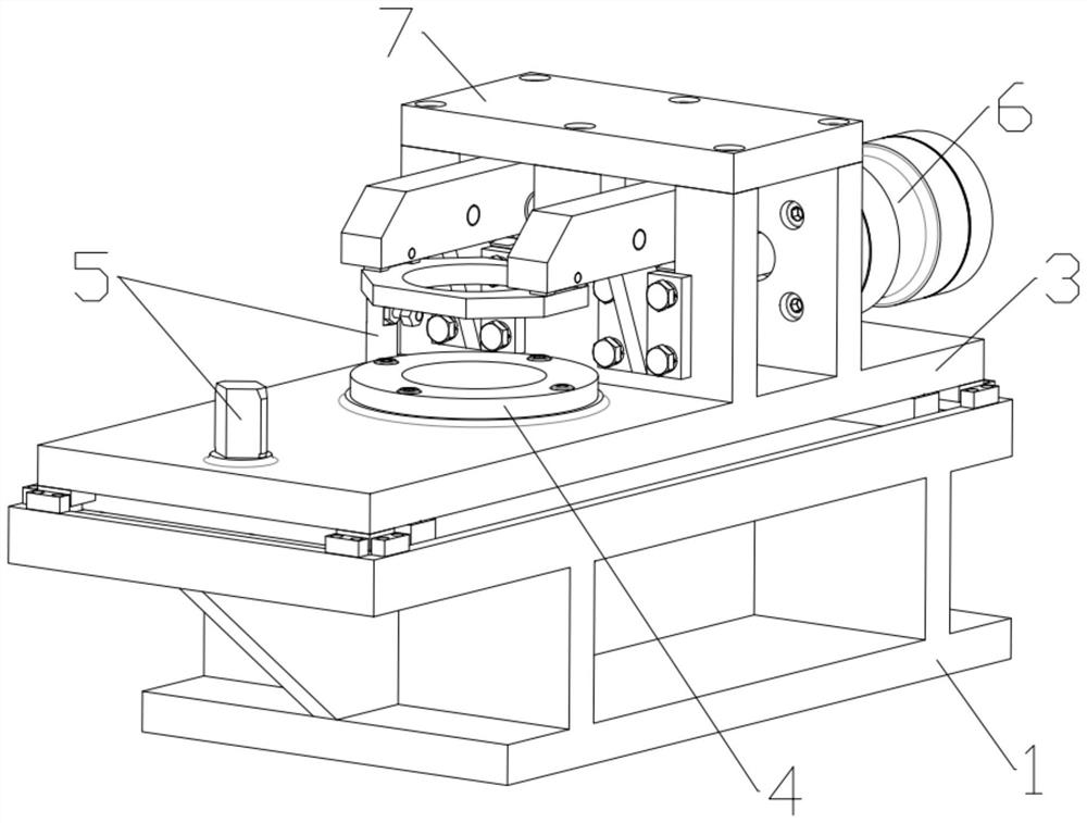
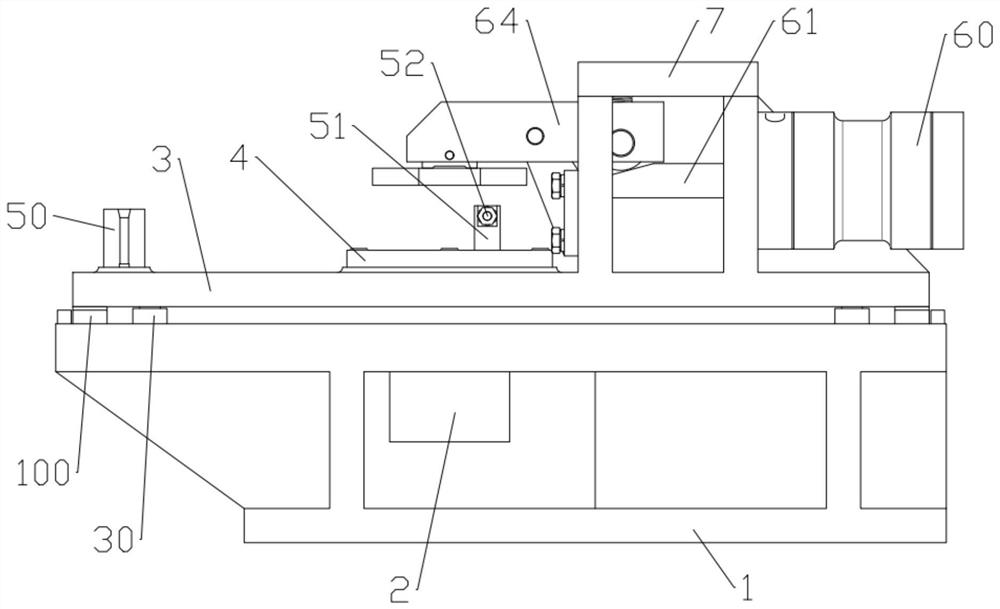
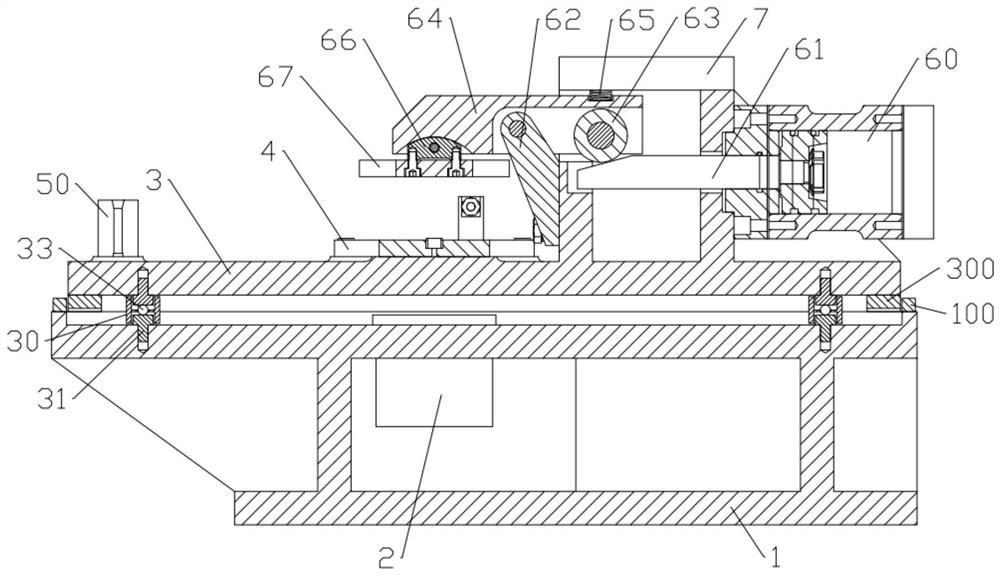
[0027] Such as Figure 1-7 As shown, in this embodiment, a floating jig for honing the big end hole of a connecting rod is composed of a base 1, a fixed guide sleeve 2, a floating plate 3, an end face positioning sleeve 4, a positioning device 5, a pneumatic clamping mechanism 6 and a square The cover plate 7 is composed of; the fixed guide sleeve 2 is a central through-hole structure and is set through the upper part of the base 1; the floating plate 3 is floatingly connected above the base 1, and the floating plate 3 can adjust the center of the big head hole by itself when honing the big head hole; the end face positioning sleeve 4 It is a central through-hole structure and is set through the middle of the floating plate 3, and the end face posi...


PUM


Abstract

The invention discloses a floating clamp for honing a connecting rod big end hole. The floating clamp comprises a base, a fixed guide sleeve, a floating plate, an end face positioning sleeve, a positioning device, a pneumatic clamping mechanism and a square cover plate. The fixed guide sleeve is of a central through hole structure and penetrates through the upper part of the base. The floating plate is connected to the upper portion of the base in a floating mode, and the floating plate can automatically adjust the center of the big end hole when the big end holeis honed. The end face positioning sleeve is of a central through hole structure and penetrates through the middle of the floating plate, the end face positioning sleeve and the fixed guide sleeve are coaxial, and the end face positioning sleeve is used for positioning the lower end face of a workpiece. The positioning device is arranged on the floating plate and is used for positioning a workpiece. The pneumatic clamping mechanism is arranged at the upper part of the floating plate and is used for clamping the workpiece. And the square cover plate is fixedly connected to the top of the floating plate. According to the clamp, shape errors during honing of the big end hole can be reduced, the size and cylindricity of the big end hole and the perpendicularity of the two end faces to the center line of the big end hole are well guaranteed, and abrasion of a connecting rod during working is relieved.

Description

technical field [0001] The invention relates to the technical field of fixtures for machining machine tools, in particular to a floating fixture for honing the big end hole of a connecting rod. Background technique [0002] At present, in the existing technology, the connecting rod parts of automobile engines are mainly formed by forging the overall blank, quenching and tempering (that is, the comprehensive heat treatment process of quenching and high temperature tempering), and machining. The impact alternating tension and compression loads and bending alternating loads generated by the reciprocating swing inertia force should have sufficient strength and rigidity. In order to obtain good performance, very high technical requirements are usually formulated when machining connecting rods, such as the center distance error of the connecting rod's big and small head holes, the distance tolerance between the two ends of the connecting rod's big and small heads, etc. [0003] I...

Claims


Application Information

Patent Timeline
Patent Type & Authority Applications(China)
IPC IPC(8): B24B41/06B24B33/02B24B33/10B24B47/06
CPCB24B41/06B24B33/02B24B33/10B24B47/06
Inventor 冯纪良
Owner CHANGZHOU INST OF MECHATRONIC TECH
Why Eureka
Try Eureka