License plate thermoprinting machine with rapid heating and stable temperature control functions

A rapid heating and hot stamping machine technology, which is applied to printing machines, rotary printing machines, printing, etc., can solve the problems of a large number of manual operations, low control precision, and bearing damage

Pending Publication Date: 2021-05-11
SICHUAN TONGAN IND
View PDF9 Cites 0 Cited by
  • Summary
  • Abstract
  • Description
  • Claims
  • Application Information

AI Technical Summary

Problems solved by technology

Because the temperature of the upper pressure roller is high, and the hot stamping of the license plate requires people to continuously put the license plate into the license plate hot stamping machine, along the front and rear of the upper pressure roller rotation direction, there are heating covers to protect the heating roller. When a person is located in the axial direction of the heating roller, there is a danger of touching the heating roller and causing burns
And after the upper pressure roller is heated, the temperature is directly transmitted to the rotating shaft. If the temperature of the rotating shaft is too high, it will cause great damage to the bearing on which the rotating shaft is installed, resulting in a reduction in the life of the license plate hot stamping machine.
[0006] In the invention patent of the license plate hot stamping equipment with the application number 201710386204.7, the name is the hot stamping equipment of the license plate controlled by the worm motor to control the rubber roller to move up and down. However, this control method still has the problem of low control accuracy, cannot realize fully automated production, and still requires a lot of manual operations

Method used


Image

  • License plate thermoprinting machine with rapid heating and stable temperature control functions
  • License plate thermoprinting machine with rapid heating and stable temperature control functions
  • License plate thermoprinting machine with rapid heating and stable temperature control functions

Examples


Embodiment Construction

[0035] The present invention will be further described below in conjunction with the accompanying drawings, but the protection scope of the present invention is not limited to the following description.

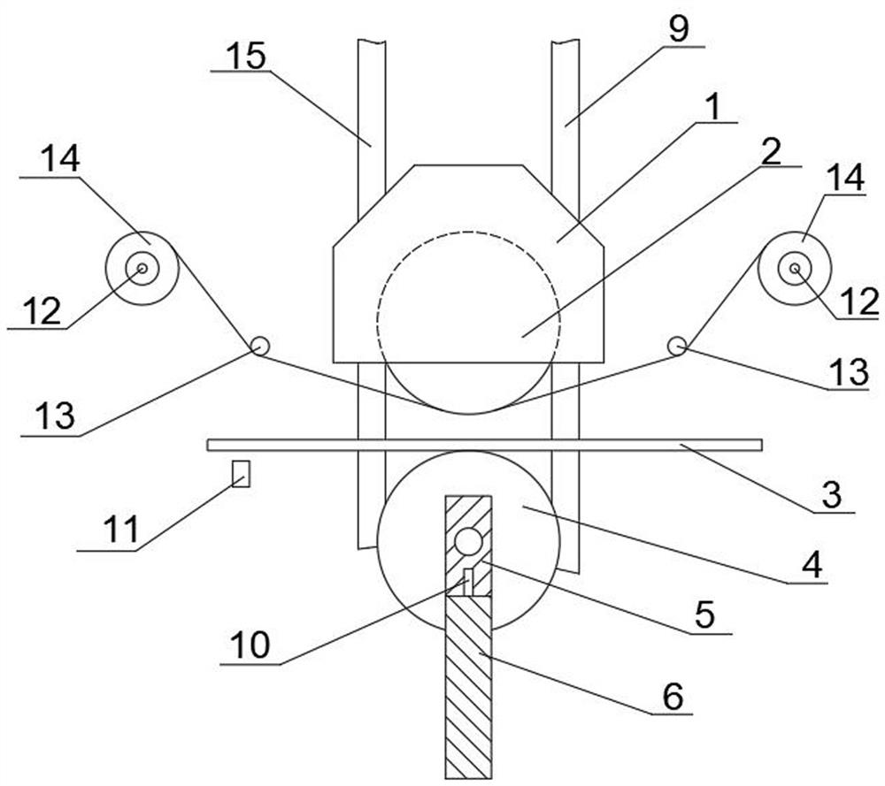
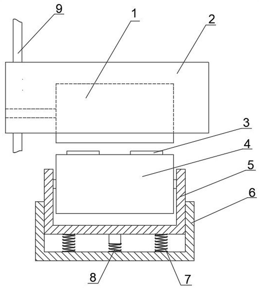
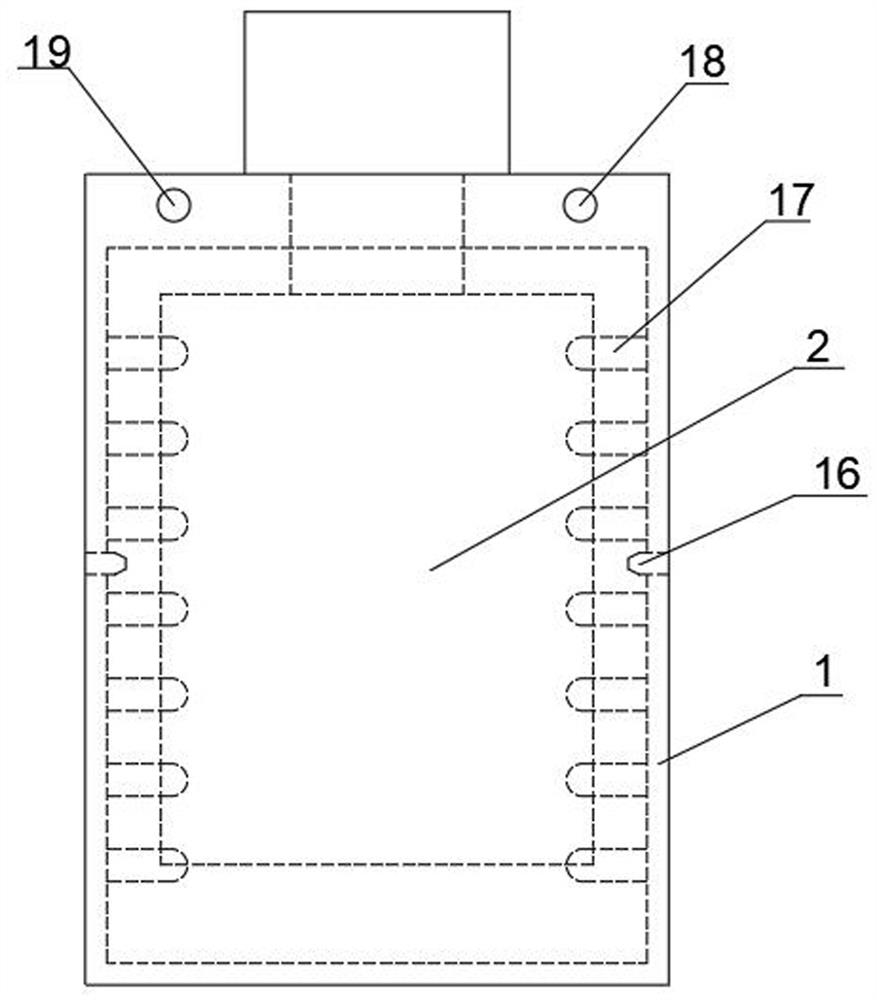
[0036] Such as Figure 1-7 As shown, a license plate hot stamping machine with rapid heating and stable temperature control includes a heating cover 1, an upper pressure roller 2, a lower pressure roller 4, a conveyor belt 3, a carbon ribbon shaft 12 and a control system, and the upper pressure roller 2 is rotatable is arranged in the heating mantle 1, the bottom of the upper pressure roller 2 protrudes from the bottom of the heating mantle 1, the conveyor belt 3 is located between the upper pressure roller 2 and the lower pressure roller 4, the rolling direction of the upper pressure roller 2 is A carbon belt shaft 12 is respectively arranged in the front and rear directions, a heating cylinder 21 is arranged in the upper pressure roller 2, the heating cover 1 is connected w...


PUM


Abstract

The invention relates to a license plate thermoprinting machine with rapid heating and stable temperature control functions. The license plate thermoprinting machine comprises a heating cover (1), an upper pressing roller (2), a lower pressing roller (4), a conveying belt (3), thermal transfer ribbon rotating shafts (12) and a control system, the upper pressing roller (2) is rotatably arranged in the heating cover (1), the conveying belt (3) is located between the upper pressing roller (2) and the lower pressing roller (4), the thermal transfer ribbon rotating shafts (12) are respectively arranged in the front direction and the rear direction of the rolling direction of the upper pressing roller (2), a heating cylinder is arranged in the upper pressing roller (2), the heating cover (1) is connected with a license plate thermoprinting machine body through a lifting structure, a pressure sensor is arranged at the bottom of the lower pressing roller (4), the signal output end of the pressure sensor is electrically connected with the control system, and the signal output end of the control system is electrically connected with the lifting structure. The pressure borne by a license plate can be regulated and controlled in real time, the hot stamping effect is ensured, waste of thermal transfer ribbons is avoided, and operators are prevented from being injured.

Description

technical field [0001] The invention relates to the technical field of vehicle license plate production, in particular to a license plate hot stamping machine with rapid heating and stable temperature control. Background technique [0002] After the license plate is molded, it is necessary to paint the license plate and hot stamp the number on the license plate. The hot stamping process of the license plate is to press the carbon belt on the license plate through the upper pressure roller, and the high temperature on the surface of the upper pressure roller makes the carbon on the carbon belt be printed on the license plate number, thus completing the hot stamping of the license plate. The hot stamping effect of the license plate is directly related to the pressure of the upper pressure roller on the license plate. When the pressure given by the upper pressure roller is insufficient, the hot stamping on the surface of the number part will be incomplete and the hot stamping e...

Claims


Application Information

Patent Timeline
Patent Type & Authority Applications(China)
IPC IPC(8): B41F16/00B41F19/06
CPCB41F16/0026B41F16/006B41F16/0073B41F19/062B41P2219/23B41P2219/31B41P2219/42
Inventor 赵子江
Owner SICHUAN TONGAN IND
Why Eureka
Try Eureka