Novel steel coil coreless cutting machine

A technology of cutting machine and steel coil, which is applied in the directions of coiling strips, thin material processing, transportation and packaging, etc., and can solve problems such as complicated operation, instability, and cumbersome unwinding process

Pending Publication Date: 2021-05-11
德州尚川自动化设备有限公司
View PDF0 Cites 0 Cited by
  • Summary
  • Abstract
  • Description
  • Claims
  • Application Information

AI Technical Summary

Problems solved by technology

[0002] With the increasing use of sheet metal today, more and more steel coils are used; when steel coils are used, they need to be uncoiled and uncoiled. The current traditional steel coil unwinding process steps are as follows: 1. The material mandrel penetrates In the inner circle cavity of the steel coil; 2. Manually tighten the core support shaft to tighten the steel coil; 3. Hoist the steel coil with the material mandrel into the rack station; 4. Open the material; the whole discharge process It is cumbersome, complicated to operate, and there are some unstable factors

Method used


Image

  • Novel steel coil coreless cutting machine
  • Novel steel coil coreless cutting machine
  • Novel steel coil coreless cutting machine

Examples


Embodiment 1

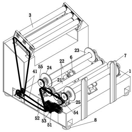
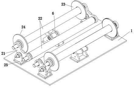
[0027] Such as Figure 1-4 As shown, a new type of steel coil coreless cutting machine includes a load frame 1 and at least two corresponding idler assemblies 2. In this embodiment, the number of idler assemblies 2 is two, and they are arranged symmetrically. The idler roller assembly 2 includes a rotating support frame 21 located on both sides and a number of rotating idler rollers 22 rotatably connected to the rotating support frame 21. The rotating idler rollers 22 on both sides form a "V"-shaped supporting space, and 9 steel coils are placed In the "V"-shaped supporting space, it is supported by several rotating idlers 22, and generates friction with several rotating idlers 22 under its own gravity, so as to realize the rotation, and because it is placed in the "V"-shaped supporting space Inside, its rotation process is very stable;

[0028] The rotating support frame 21 is connected to the idler base 25 by rotating pins, so that it can swing within a certain range, there...

Embodiment 2

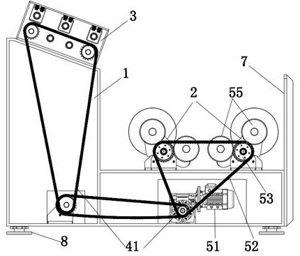
[0031] On the basis of Example 1, such as figure 1 , figure 2 , Figure 6 , Figure 7 As shown, one end (i.e., the discharge end) of the carrying frame 1 is also provided with a traction mechanism 3, and the traction mechanism 3 includes several upper rollers 31 arranged in parallel, several lower rollers 32 and two side roller bracket 33, the two ends of the upper roller shaft 31 and the lower roller shaft 32 are rotatably connected to the roller shaft bracket 33, wherein several lower roller shafts 32 are synchronously driven to rotate through the first transmission system 41, and the second A transmission system 41 is a first chain transmission system, and the drive element 51 drives several lower roller shafts 32 to rotate synchronously through the first chain transmission system at the same time, and the material sheet passes between the upper roller shaft 31 and the lower roller shaft 32, The forward traction movement of the tablet is realized by friction.

[0032] ...


PUM


Abstract

The invention belongs to the technical field of steel coil uncoiling, and particularly relates to a novel steel coil coreless cutting machine. The novel steel coil coreless cutting machine comprises a bearing rack and at least two carrier roller assemblies arranged correspondingly, each carrier roller assembly comprises rotating supporting frames located on the two sides and a plurality of rotating carrier rollers rotationally connected to the rotating supporting frames, the rotating carrier rollers on the two sides form "a V-shaped bearing space", and the rotating carrier rollers on the two sides are synchronously driven to rotate through a carrier roller driving mechanism. The novel steel coil coreless cutting machine is simple in structure, the cutting machine is not provided with a core shaft, a steel coil is directly hoisted to the carrier roller assembly of the cutting machine through a crane, the process of installing the core shaft is omitted, a lot of preparation time is saved, and the direct hoisting method also greatly reduces the danger generated during the installation of the steel coil, and has the advantages of being convenient to operate, time-saving and labor-saving in installation, safe, stable and the like.

Description

technical field [0001] The invention belongs to the technical field of steel coil uncoiling, and relates to a novel steel coil coreless cutting machine. Background technique [0002] With the increasing use of sheet metal today, more and more steel coils are used; when steel coils are used, they need to be uncoiled and uncoiled. The current traditional steel coil unwinding process steps are as follows: 1. The material mandrel penetrates In the inner circle cavity of the steel coil; 2. Manually tighten the core support shaft to tighten the steel coil; 3. Hoist the steel coil with the material mandrel into the rack station; 4. Open the material; the whole discharge process It is cumbersome, complicated to operate, and there are some unstable factors. Contents of the invention [0003] The invention provides a new steel coil coreless cutting machine, which can solve the problems pointed out in the background technology. [0004] A new type of steel coil coreless cutting mac...

Claims


Application Information

Patent Timeline
Patent Type & Authority Applications(China)
IPC IPC(8): B65H16/08B65H16/10B65H19/12
CPCB65H16/08B65H16/106B65H19/12B65H2701/1133B65H2701/173
Inventor 程继华马冬勇朱浩然
Owner 德州尚川自动化设备有限公司
Why Eureka
Try Eureka