
Worm and gear transmission structure

A transmission structure, worm gear technology, applied in the direction of gear transmission, transmission, transmission parts, etc., can solve the problems of reduced transmission accuracy, high processing cost, high processing accuracy requirements, etc., to achieve reduced processing accuracy requirements and reduced manufacturing costs , Guarantee the effect of transmission accuracy

Pending Publication Date: 2021-05-11
SANLI VIDEO FREQUENCY SCI & TECH SHENZHEN
View PDF0 Cites 0 Cited by
  • Summary
  • Abstract
  • Description
  • Claims
  • Application Information

AI Technical Summary

Problems solved by technology

[0002] In transmission design, due to special requirements, such as mechanism self-locking, large transmission ratio, etc., it is necessary to use worm gear transmission. Now the fixed center distance is generally used to design the worm gear transmission structure. In order to achieve high transmission accuracy, each structural part is processed High precision requirements lead to high processing costs, and if the processing accuracy requirements are lowered, there will be backlash in the meshing state of the worm gear, so that the transmission accuracy will be reduced

Method used


Image

  • Worm and gear transmission structure
  • Worm and gear transmission structure

Examples


Embodiment 1

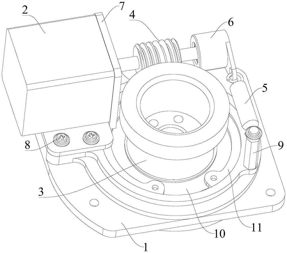
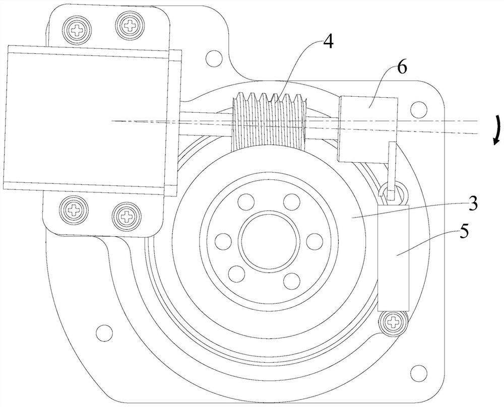
[0037] Please refer to figure 1 and figure 2 , Embodiment 1 of the present invention is: a worm gear transmission structure, including a mounting base 1, a motor 2, and a matched worm wheel 3 and a worm 4, the output end of the motor 2 is connected to one end of the worm 4, and the The worm wheel 3 is rotated and installed on the mounting base 1, the motor 2 is movable on the mounting base 1, and also includes an elastic member 5, a first bearing and a bearing seat 6, and the first bearing is sleeved on the worm 4 The other end of the elastic member 5 is fixed on the bearing seat 6, one end of the elastic member 5 is connected to the mounting seat 1, and the other end of the elastic member 5 is connected to the bearing seat 6 to drive the worm 4 close to the worm gear 3. Optionally, the elastic member 5 is a tension spring.

[0038] In this embodiment, the worm gear transmission structure further includes a mounting frame 7 on which the motor 2 is fixed, and the mounting f...


PUM


Abstract

The invention discloses a worm and gear transmission structure. The worm and gear transmission structure comprises a mounting seat, a motor, a worm and a gear, wherein the worm and the gear are matched with each other, the output end of the motor is connected with one end of the gear, the worm is rotatably arranged on the mounting seat, the motor is movably arranged on the mounting seat, and the worm and gear transmission structure further comprises an elastic part, a first bearing and a bearing seat; and the first bearing sleeves the other end of the gear and fixed to the bearing seat, one end of the elastic part is connected with the mounting seat, and the other end of the elastic part is connected with the bearing seat so as to drive the gear to be close to the worm. Under the action of the elastic part, the worm and the motor can deflect by a certain angle, so that the center distance of the worm and the gear is automatically adjusted, zero-meshing backlash transmission of the worm and the gear is achieved, and the transmission precision of the worm and the gear is effectively guaranteed; and due to the fact that the center distance of the worm and the gear can be automatically adjusted, the machining precision requirement of the worm and the gear can be lowered, and the manufacturing cost of the worm and gear transmission structure is reduced.

Description

technical field [0001] The invention relates to the technical field of transmission structures, in particular to a worm gear transmission structure. Background technique [0002] In transmission design, due to special requirements, such as mechanism self-locking, large transmission ratio, etc., it is necessary to use worm gear transmission. Now the fixed center distance is generally used to design the worm gear transmission structure. In order to achieve high transmission accuracy, each structural part is processed High precision requirements lead to high processing costs, and if the processing precision requirements are lowered, there will be backlash in the meshing state of the worm gear, so that the transmission precision will be reduced. Contents of the invention [0003] The technical problem to be solved by the present invention is to provide a worm gear transmission structure with high transmission precision and low processing cost. [0004] In order to solve the a...

Claims


Application Information

Patent Timeline
IPC IPC(8): F16H1/16F16H57/021F16H57/12
CPCF16H1/16F16H57/021F16H57/12F16H2057/0213
Inventor 刘样张宇周涛杨伟强
Owner SANLI VIDEO FREQUENCY SCI & TECH SHENZHEN
Learn More