
Optical thin film testing method and equipment

An optical film and testing method technology, applied in the field of lasers, can solve the problems of low degree of automation and inaccurate measurement results.

Active Publication Date: 2021-05-11
深圳市桓日激光有限公司
View PDF6 Cites 0 Cited by
  • Summary
  • Abstract
  • Description
  • Claims
  • Application Information

AI Technical Summary

Problems solved by technology

The existing measurement method requires manual participation in the whole process, the degree of automation is relatively low, and the measurement results are not accurate enough

Method used

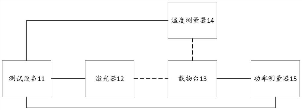

Image

  • Optical thin film testing method and equipment
  • Optical thin film testing method and equipment
  • Optical thin film testing method and equipment

Examples


Embodiment Construction

[0051] In order to make the object, technical solution and advantages of the present invention clearer, the present invention will be further described in detail below in conjunction with the accompanying drawings and embodiments. It should be understood that the specific embodiments described here are only used to explain the present invention, not to limit the present invention. Based on the embodiments of the present invention, all other embodiments obtained by persons of ordinary skill in the art without creative efforts fall within the protection scope of the present invention.

[0052] It should be noted that, if there is no conflict, various features in the embodiments of the present invention may be combined with each other, and all of them are within the protection scope of the present invention. In addition, although the functional modules are divided in the schematic diagram of the device, and the logical order is shown in the flowchart, in some cases, the division ...


PUM

PropertyMeasurementUnit
laser radiation transmissionaaaaaaaaaa

Abstract

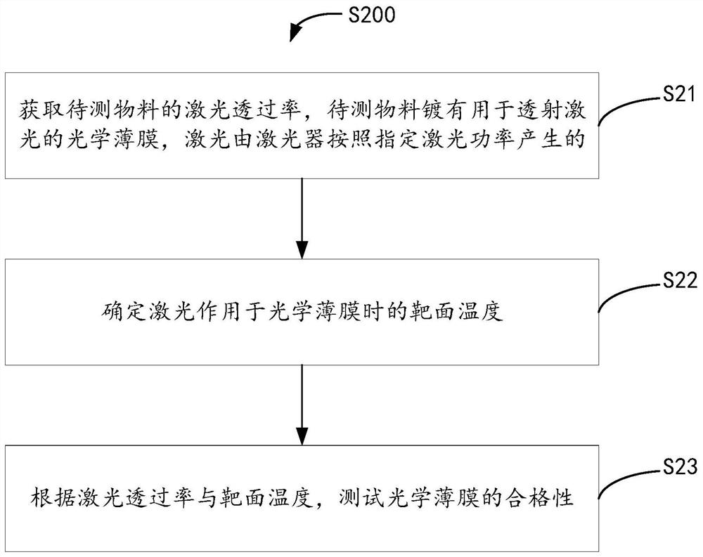
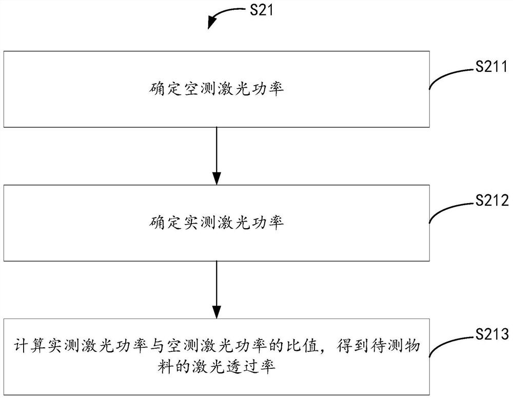
The invention relates to the technical field of lasers, and discloses an optical thin film testing method and equipment. The optical thin film testing method comprises the following steps: obtaining the laser transmittance of a to-be-tested material, wherein the to-be-tested material is plated with an optical thin film used for transmitting laser, and the laser is generated by a laser according to specified laser parameters; determining the target surface temperature when the laser acts on the optical thin film; and testing the qualification of the optical film according to the laser transmittance and the target surface temperature. Therefore, according to the method, the laser transmittance and the target surface temperature can be automatically utilized to measure the qualification of the optical thin film, the participation of human factors is reduced as much as possible, the accuracy of a measurement result is improved, and the measurement time is saved.

Description

technical field [0001] The invention relates to the technical field of lasers, in particular to an optical thin film testing method and testing equipment. Background technique [0002] In order to improve the output energy and output characteristics of the laser, and eliminate the influence of stray light in the laser on the optical components inside the laser, optical thin films are widely used in various lasers. Among them, the damage threshold of the optical film is an important factor to limit the output intensity of the laser and measure the safe operation of the laser system. [0003] In the actual damage measurement of optical thin films, various companies or scientific research institutions often use different spot sizes and different laser wavelengths according to their actual needs, combined with different damage judgment methods for measurement. The existing measurement method requires manual participation in the whole process, the degree of automation is relativ...

Claims


Application Information

Patent Timeline
Patent Type & Authority Applications(China)
IPC IPC(8): G01N21/59
CPCG01N21/59Y02E10/50
Inventor 吕张勇曾庆坤李广杰李永高邱小兵周凯斌屈浩田李昌席蒋峰
Owner 深圳市桓日激光有限公司
Learn More