
Revit-based electrical system diagram generation method

A technology for electrical systems and meter boxes, applied in CAD circuit design, special data processing applications, etc., can solve problems such as separation of drawing work and design work, separation of design processes, and inability to meet standardized drawings.

Pending Publication Date: 2021-05-11
TONGJI UNIV ARCHITECTURAL DESIGN INST GRP CO LTD
View PDF4 Cites 1 Cited by
  • Summary
  • Abstract
  • Description
  • Claims
  • Application Information

AI Technical Summary

Problems solved by technology

[0002] When drawing the existing electrical system diagram, the method of plane drawing is often used in the three-dimensional modeling software, the electrical system diagram is manually drawn, and then the parameter design is carried out, and finally the drawing is generated. The drawing work is separated from the design work, and the efficiency is low
Various parameters such as system components, switch selection, wire selection, etc. are manually input, and the selection and calculation are generally carried out in various forms summarized by other designers, resulting in the generation and drawing of electrical system diagrams and the selection of electrical systems. Model and design process are separated, drawing efficiency is low, and it cannot meet the requirements of standardized drawing

Method used


Image

  • Revit-based electrical system diagram generation method
  • Revit-based electrical system diagram generation method
  • Revit-based electrical system diagram generation method

Examples


Embodiment

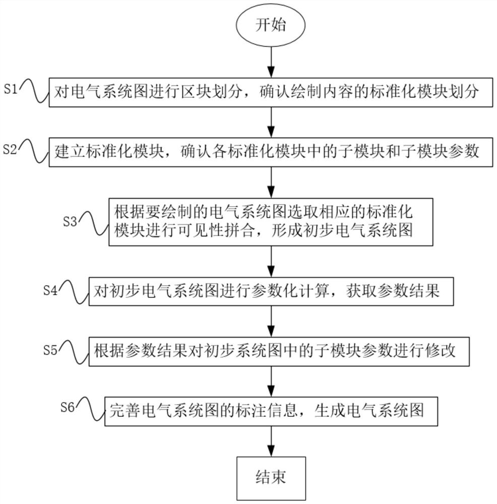
[0042] A Revit-based electrical system diagram generation method, such as figure 1 shown, including the following steps:

[0043] S1: Divide the electrical system diagram into blocks, and confirm the standardized module division of the drawn content;

[0044] S2: Establish standardized modules, and confirm submodules and submodule parameters in each standardized module.

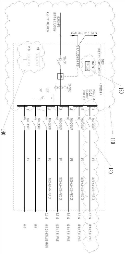
[0045] In the present invention, the standardized modules obtained by division include a single-incoming bus-side module 110, a double-incoming bus-side module 150, a circuit-side module 120, a centralized emergency lighting power supply module 160, an electric meter box module 130, and a box grounding module 140.

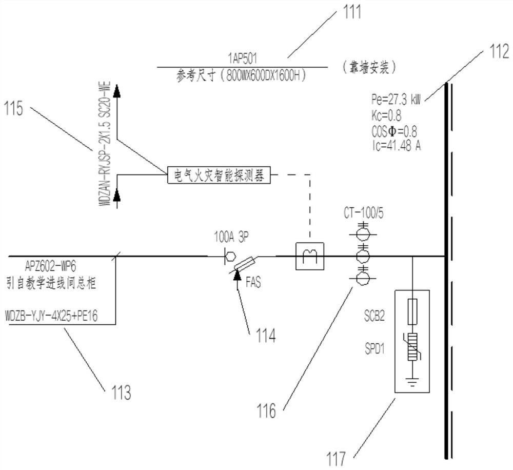
[0046] Specifically, in this embodiment, as Figure 2-6 As shown, the submodules and parameter information included in each module are as follows:

[0047] The single incoming line busbar side module 110 includes a cabinet information sub-module 111, a power distribution calculation sub-module ...


PUM


Abstract

The invention relates to a Revit-based electrical system diagram generation method, and the method comprises: S1, carrying out the block division of an electrical system diagram, and confirming the standardized module division of drawing content; S2, establishing standardized modules, and confirming sub-modules and sub-module parameters in each standardized module; S3, selecting corresponding standardized modules according to the electrical system diagram to be drawn to carry out visible splicing so as to form a preliminary electrical system diagram; S4, performing parameterization calculation on the initial electrical system diagram to obtain a parameter result; S5, modifying sub-module parameters in the preliminary system diagram according to a parameter result; and S6, completing the labeling information of the electrical system diagram, and generating the electrical system diagram. Compared with the prior art, the method is advantageous in that, on the basis of establishment, splicing, calculation and adjustment of the standardized modules, the electrical system can be generated in a standardized, modularized and normalized mode, the application range is wide, the drawing efficiency is high, and the requirement for standardized drawing is met.

Description

technical field [0001] The invention relates to a method for generating electrical system diagrams, in particular to a method for generating electrical system diagrams based on Revit. Background technique [0002] When drawing the existing electrical system diagram, the method of plane drawing is often used in the three-dimensional modeling software, the electrical system diagram is manually drawn, and then the parameter design is performed, and finally the drawing is generated. The drawing work is separated from the design work, which is inefficient. Various parameters such as system components, switch selection, wire selection, etc. are manually input, and the selection and calculation are generally carried out in various forms summarized by other designers, resulting in the generation and drawing of electrical system diagrams and the selection of electrical systems. Model and design processes are separated, drawing efficiency is low, and it cannot meet the requirements of...

Claims


Application Information

Patent Timeline
IPC IPC(8): G06F30/39
CPCG06F30/39
Inventor 张陆陆张东升刘建牛传奇卫界岑
Owner TONGJI UNIV ARCHITECTURAL DESIGN INST GRP CO LTD
Learn More